Non Destructive Testing Of Structures

Abstract
Non Destructive Testing Of Structures
A large range of Non-Destructive Testing (NDT) techniques are employed for a wide variety of applications within Civil Engineering. The majority of these applications may be regarded as structural but they also include site surveying and highways problems. Testing may be used during planning and construction phases, but the majorities of applications are concerned with troubleshooting, maintenance and repair. The normal maintenance method is to inspect the structure periodically, and when the degrees of deterioration exceed certain limit, repair or strengthening of the structures is performed. To inspect existing structures, visual inspection is the easiest and the most fundamental method. But this method may not be applicable for inspecting defects which does not appear on the surface. For such defects, Non-destructive inspection is the only method which can be applied. Nondestructive testing plays an important role for quality evaluation. India has been producing concrete structures since long times. And now it is becoming important problem to maintain these existing concrete and steel structures. This presentation aims on the explanation of NDT techniques and their application to structures.
Contents
- Introduction 1
- Destructive testing 2
2.1 Definitions of Hardness . . . . . . . . . . . . . . . . . . . . . . . . . . . . . . 2
2.2 Testing of large structures . . . . . . . . . . . . . . . . . . . . . . . . . . . . 3
2.3 Destructive software testing . . . . . . . . . . . . . . . . . . . . . . . . . . . 3
- Non Destructive Testing 5
- Ultrasonic testing 7
4.1 How it works . . . . . . . . . . . . . . . . . . . . . . . . . . . . . . . . . . . 7
- Liquid Penetration Test 10
- Magnetic Particle inspection 14
- ElectroMagnetic testing 17
- Radiographic Testing 20
- Miscellaneous methods 23
- Case Study: Bridge
- Conclusions
List of Figures
2.1 Destructive testing of a 6-story non-ductile concrete building using a shake table[2]
5.1 Dye penetration test Steps[3]
- X-Ray Equipment[8]
- X-Ray image of reinforced concrete column[9]
9.1 Carrying of RADAR Test on pavement[5]
- Schmidt Hammer[7],GPR Test being conducted on a bridge[5]
- Figure showing the RADAR data[5]
Chapter 1 Introduction
Nondestructive testing (NDT) is a wide group of analysis techniques used in science and industry to evaluate the properties of a material, component or system without causing damage. Because NDT does not permanently alter the article being inspected, it is a highly- valuable technique that can save both money and time in product evaluation, troubleshoot- ing, and research. Common NDT methods include ultrasonic, magnetic-particle, liquid pen- etrant, radiographic, and eddy-current testing NDT is a commonly-used tool in forensic engineering, mechanical engineering, electrical engineering, civil engineering, systems engi- neering, medicine, and art. Specialist high risk areas such as nuclear and offshore structures, and gas and oil pipelines, make extensive use of Non-Destructive Testing of metallic compo- nents during manufacture and construction as part of quality assurance procedures as well as during routine maintenance inspections to detect cracking and corrosion. Radiography and ultrasonics are most widely used for checking of welds, although eddy current and magnetic methods are also available. Alternating current field measurement techniques permit non- contacting crack detection and sizing in welded joints both in air and underwater.The focus of this presentations concentrates on mainstream engineering activities, where the extent of
N.D.T. usage varies considerably [1].
Chapter 2 Destructive testing
In destructive testing, tests are carried out to the specimen’s failure, in order to understand a specimen’s structural performance or material behavior under different loads. These tests are generallymuch easier to carry out, yield more information, and are easier to interpret than nondestructive testing. Destructive testing is most suitable, and economic, for objects which will be mass produced, as the cost of destroying a small number of specimens is negligible. It is usually not economic to do destructive testing where only one or very few items are to be produced (for example, in the case of a building). Some types of destructive testing.
Stress testing: It is a form of testing that is used to determine the stability of a given system or entity. It involves testing beyond normal operational capacity, often to a breaking point, in order to observe the results. Stress testing may have a more specific meaning in certain industries, such as fatigue testing for materials.
Crash testing: It is a form of destructive testing usually performed in order to ensure safe design standards in crashworthiness and crash compatibility for automobiles or related components. Some of the examples are Frontal-Impact Tests, Offset Tests, and Side-Impact Tests, Roll over Tests, Roadside hardware crash tests e.t.c. The tests are not discussed here as it is beyond the scope of this presentation
Hardness testing: Hardness refers to various properties of matter in the solid phase that gives it high resistance to various kinds of shape change when force is applied. Macroscopic hardness is generally characterized by strong intermolecular bonds. How- ever, the behavior of solid materials under force is complex, resulting in several different scientific definitions of what might be called ”hardness” in everyday usage.
Definitions of Hardness
In materials science, there are three principal operational definitions of hardness.
Scratch hardness: Resistance to fracture or plastic (permanent) deformation due to friction from a sharp object.
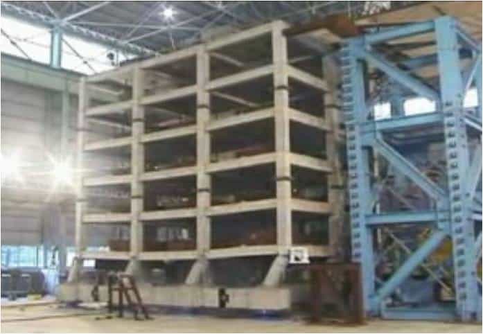
Figure 2.1: Destructive testing of a 6-story non-ductile concrete building using a shake table[2]
Indentation hardness: Resistance to plastic (permanent) deformation due to a con- stant load from a sharp object.
•Rebound hardness: Height of the bounce of an object dropped on the material, related to elasticity.
•The mathematical definition of hardness is the pressure applied over the projected contact area between the indenter and the material being tested. As a result hardness values are typically reported in units of pressure, although this is only a ”true” pressure if the indenter and surface interface is perfectly flat[2].
Testing of large structures
Building structures or large nonbuilding structures (such as dams and bridges) are rarely subjected to destructive testing due to the prohibitive cost of constructing a building, or a scale model of a building, just to destroy it. Earthquake engineering requires a good understanding of how structures will perform at earthquakes. Destructive tests are more frequently carried out for structures which are to be constructed in earthquake zones. Such tests are sometimes referred to as crash tests, and they are carried out to verify the designed seismic performance of a new building, or the actual performance of an existing building. The tests are, mostly, carried out on a platform called a shake-table which is designed to shake in the same manner as an earthquake(Fig. 2.1).
Destructive software testing
Destructive software testing is a type of software testing which attempts to cause a piece of software to fail in an uncontrolled manner, in order to test its robustness. As structural performance at earthquakes is better understood, testing of structures in earthquakes is increasingly done by modeling the structure using specialist finite element software[2].
Chapter 3
Non Destructive Testing
Nondestructive testing (NDT) are noninvasive techniques to determine the integrity of a material, component or structure or quantitatively measure some characteristic of an object. In contrast to destructive testing, NDT is an assessment without doing harm, stress or de- stroying the test object. The destruction of the test object usually makes destructive testing more costly and it is also inappropriate in many circumstances. NDT plays a crucial role in ensuring cost effective operation, safety and reliability of plant, with resultant benefit to the community. NDT is used in a wide range of industrial areas and is used at almost any stage in the production or life cycle of many components. The mainstream applications are in aerospace and civil structures, power generation, automotive, railway, petrochemical and pipeline markets. NDT of welds is one of the most used applications. It is very difficult to weld or mold a solid object that has no risk of breaking in service, so testing at manufacture and during use is often essential.
While originally NDT was applied only for safety reasons it is today widely ac- cepted as cost saving technique in the quality assurance process. Unfortunately NDT is still not used in many areas where human life or ecology is in danger. Some may prefer to pay the lower costs of claims after an accident than applying of NDT. That is a form of unacceptable risk management.
For implementation of NDT it is important to describe what shall be found and what to reject. A completely flawless production is almost never possible. For this reason testing specifications are indispensable. Nowadays there exists a great number of standards and acceptance regulations. They describe the limit between good and bad conditions, but also often which specific NDT method has to be used. The reliability of an NDT Method is an essential issue. But a comparison of methods is only significant if it is referring to the same task. Each NDT method has its own set of advantages and disadvantages and, therefore, some are better suited than others for a particular application. By use of artificial flaws, the threshold of the sensitivity of a testing system has to be determined. If the the sensitivity is to low defective test objects are not always recognized. If the sensitivity is too high parts with smaller flaws are rejected which would have been of no consequence to the serviceability of the component. With statistical methods it is possible to look closer into the field of uncertainly. Methods such as Probability of Detection (POD) or the ROC-method ”Relative Operating Characteristics” are examples of the statistical analysis methods. Also the aspect of human errors has to be taken into account when determining the overall reli- ability. Personnel Qualification is an important aspect of non-destructive evaluation. NDT techniques rely heavily on human skill and knowledge for the correct assessment and inter- pretation of test results. Proper and adequate training and certification of NDT personnel is therefore a must to ensure that the capabilities of the techniques are fully exploited. There are a number of published international and regional standards covering the certification of competence of personnel.
The most common NDT Methods are discussed in this presentation. In order of most used, they are: Ultrasonic Testing (UT), Radiographic Testing (RT), Liquid penetrant Testing, Magnetic particle Testing, Electromagnetic Testing (ET) in which Eddy Current Testing (ECT) is well know and Acoustic Emission (AE or AET). Besides the main NDT methods a lot of other NDT techniques are available, such as Shearography Holography, Microwave and many more and new methods are being constantly researched and developed. In the next sections the methods are explained and their applications to structures are discussed[3].
Chapter 4 Ultrasonic testing
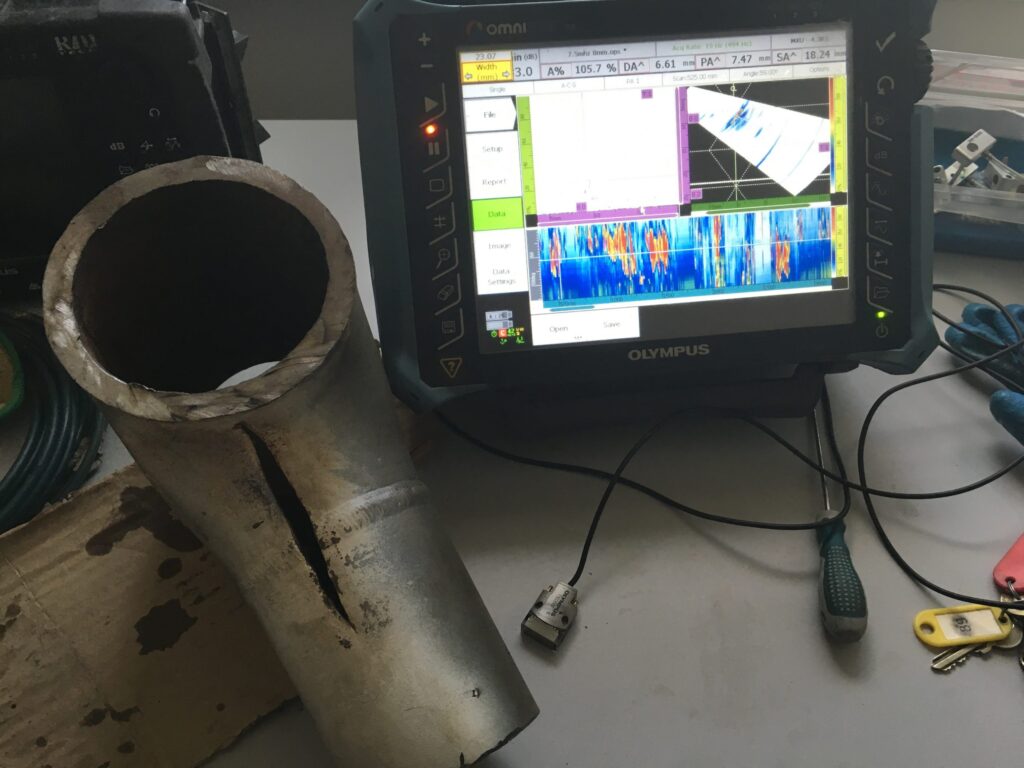
In ultrasonic testing, very short ultrasonic pulse-waves with center frequencies ranging from 0.1-15 MHz and occasionally up to 50 MHz are launched into materials to detect internal flaws or to characterize materials. The technique is also commonly used to determine the thickness of the test object, for example, to monitor pipework corrosion. Ultrasonic testing is often performed on steel and other metals and alloys, though it can also be used on concrete, wood and composites, albeit with less resolution. It is a form of non destructive testing used in many industries including aerospace, automotive and other transportation sectors[3].
How it works
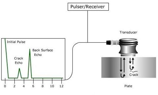
In ultrasonic testing, an ultrasound transducer connected to a diagnostic machine is passed over the object being inspected. The transducer is typically separated from the test object by a couplant (such as oil) or by water, as in immersion testing.
There are two methods of receiving the ultrasound waveform, reflection and at- tenuation. In reflection (or pulse-echo) mode, the transducer performs both the sending and the receiving of the pulsed waves as the ”sound” is reflected back to the device. Reflected ul- trasound comes from an interface, such as the back wall of the object or from an imperfection within the object. The diagnostic machine displays these results in the form of a signal with an amplitude representing the intensity of the reflection and the distance, representing the arrival time of the reflection. In attenuation (or through-transmission) mode, a transmitter sends ultrasound through one surface, and a separate receiver detects the amount that has reached it on another surface after traveling through the medium. Imperfections or other conditions in the space between the transmitter and receiver reduce the amount of sound transmitted, thus revealing their presence
Advantages:
- High penetrating power, which allows the detection of flaws deep in the part.
- High sensitivity, permitting the detection of extremely small flaws.
- Only one surface need be accessible.
Greater accuracy than other nondestructive methods in determining the depth of in- ternal flaws and the thickness of parts with parallel surfaces.
- Some capability of estimating the size, orientation, shape and nature of defects.
Nonhazardous to operations or to nearby personnel and has no effect on equipment and materials in the vicinity.
- Capable of portable or highly automated operation.
- metals, nonmetals and composites
- surface and slightly subsurface flaws can be detected
can be applied to welds, tubing, joints, castings, billets, forgings, shafts, structural components, concrete, pressure vessels, aircraft and engine components
- used to determine thickness and mechanical properties
- monitoring service wear and deterioration
Disadvantages:
- Manual operation requires careful attention by experienced technicians
- Extensive technical knowledge is required for the development of inspection procedures
Parts that are rough, irregular in shape, very small or thin, or not homogeneous are difficult to inspect.
Surface must be prepared by cleaning and removing loose scale, paint, etc, although paint that is properly bonded to a surface usually need not be removed.
Couplants are needed to provide effective transfer of ultrasonic wave energy between transducers and parts being inspected unless a non-contact technique is used. Non- contact techniques include Laser and Electro Magnetic Acoustic Transducers (EMAT).
Inspected items must be water resistant, when using water based couplants that do not contain rust inhibitors.
usually contacting, either direct or with intervening medium required (e.g. immersion testing)
- special probes are required for applications
- sensitivity limited by frequency used and some materials cause significant scattering
- scattering by test material structure can cause false indications
- not easily applied to very thin materials
Chapter 5
Liquid Penetration Test
Dye penetrant inspection (DPI), also called liquid penetrant inspection (LPI), is a widely ap- plied and low-cost inspection method used to locate surface-breaking defects in all non-porous materials (Can be applied to welds, tubing, castings, forgings, aluminum parts, turbine blades and disks, gears, metals, plastics). The penetrant may be applied to all non-ferrous materials, but for inspection of ferrous components magnetic-particle inspection is preferred for its subsurface detection capability. LPI is used to detect casting and forging defects, cracks, and leaks in new products, and fatigue cracks on in-service components.The merits of this technique are,Limited training is required for the operator – (although experience is quite valuable), Low testing costs.
Principle
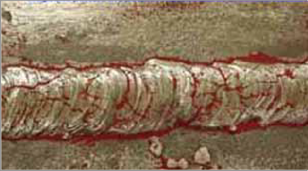
DPI is based upon capillary action, where low surface tension fluid penetrates into clean and dry surface-breaking discontinuities. Penetrant may be applied to the test component by dipping, spraying, or brushing. After adequate penetration time has been allowed, the excess penetrant is removed, a developer is applied. The developer helps to draw penetrant out of the flaw where a visible indication becomes visible to the inspector. Inspection is performed under ultraviolet or white light, depending upon the type of dye used – fluorescent or nonfluorescent (visible).
Materials
Penetrants are classified into sensitivity levels. Visible penetrants are typically red in color, and represent the lowest sensitivity. Fluorescent penetrants contain two or more dyes that fluoresce when excited by ultraviolet (UV-A) radiation (also known as black light). Since Fluorescent penetrant inspection is performed in a darkened environment, and the excited dyes emit brilliant yellow-green light that contrasts strongly against the dark background, this material is more sensitive to small defects. When selecting a sensitivity level one must consider many factors, including the environment under which the test will be performed, the surface finish of the specimen, and the size of defects sought. One must also assure that the test chemicals are compatible with the sample so that the examination will not cause permanent staining, or degradation. This technique can be quite portable, because in its simplest form the inspection requires only 3 aerosol spray cans, some paper towels, and ad- equate visible light. Stationary systems with dedicated application, wash, and development stations, are more costly and complicated, but result in better sensitivity and higher sample through-put.
Procedure
Below are the main steps of Liquid Penetrant Inspection: 1. Pre-cleaning: The test sur- face is cleaned to remove any dirt, paint, oil, grease or any loose scale that could either keep penetrant out of a defect, or cause irrelevant or false indications. Cleaning methods may include solvents, alkaline cleaning steps, vapor degreasing. The end goal of this step is a clean surface where any defects present are open to the surface, dry, and free of contamina- tion. 2. Application of Penetrant: The penetrant is then applied to the surface of the item being tested. The penetrant is allowed time to soak into any flaws (generally 5 to 30 minutes). The dwell time mainly depends upon the penetrant being used, material being testing and the size of flaws sought. As expected, smaller flaws require a longer penetration time 3. Excess Penetrant Removal: The excess penetrant is then removed from the surface. The removal method is controlled by the type of penetrant used. Water-washable, solvent-removable, lipophilic post-emulsifiable, or hydrophilic post-emulsifiable are the com- mon choices. Emulsifiers represent the highest sensitivity level, and chemically interact with the oily penetrant to make it removable with a water spray. When using solvent remover and lint-free cloth it is important to not spray the solvent on the test surface directly, because this can the remove the penetrant from the flaws. This process must be performed under controlled conditions so that all penetrant on the surface is removed (background noise), but penetrants trapped in real defects remains in place.
4. Application of Developer: After excess penetrant has been removed a white devel-
oper is applied to the sample. Several developer types are available, including: non-aqueous wet developer, dry powder, water suspendable, and water soluble. Choice of developer is governed by penetrant compatibility (one can’t use water-soluble or suspendable developer with water-washable penetrant), and by inspection conditions. When using non-aqueous wet developer (NAWD) or dry powder, the sample must be dried prior to application, while soluble and suspendable developers are applied with the part still wet from the previous step. NAWD is commercially available in aerosol spray cans, and may employ acetone, iso- propyl alcohol, or a propellant that is a combination of the two. Developer should form a semi-transparent, even coating on the surface. The developer draws penetrant from defects out onto the surface to form a visible indication, a process similar to the action of blotting paper. Any colored stains indicate the positions and types of defects on the surface under inspection. 5. Inspection: The inspector will use visible light with adequate intensity (100 foot-candles or 1100 lux is typical) for visible dye penetrant. Ultraviolet (UV-A) radiation of adequate intensity (1,000 micro-watts per centimeter squared is common), along with low ambient light levels (less than 2 foot-candles) for fluorescent penetrant examinations. Inspection of the test surface should take place after a 10 minute development time. This time delay allows the blotting action to occur. The inspector may observe the sample for indication formation when using visible dye. Also of concern, if one waits too long after development, the indications may ”bleed out” such that interpretation is hindered. 6. Post Cleaning: The test surface is often cleaned after inspection and recording of defects, espe- cially if post-inspection coating processes are scheduled. The flaws are more visible, because The defect indication has a high visual contrast (e.g. red dye against a white developer background, or a bright fluorescent indication against a dark background). The developer draws the penetrant out of the flaw over a wider area than the real flaw, so it looks wider[2].
Limitations
- need access to test surface
- efects must be surface breaking
- decontamination and precleaning of test surface may be needed
- vapour hazard.
- very tight and shallow defects difficult to find
- depth of flaw not indicated
Precautions
Proper cleaning is necessary to assure that surface contaminants have been removed and any defects present are clean and dry. Some cleaning methods have been shown to be detrimental to test sensitivity, so acid etching to remove metal smearing and re-open the defect may be necessary. Penetrant dyes stain cloth, skin and other porous surfaces brought into contact. One should verify compatibility on the test material, especially when considering the testing of plastic components.
Steps,Fig 5.1
- 1.Section of material with a surface-breaking crack that is not visible to the naked eye.
- 2.Penetrant is applied to the surface.
- 3.Excess penetrant is removed.
- 4.Developer is applied, rendering the crack visible.
13
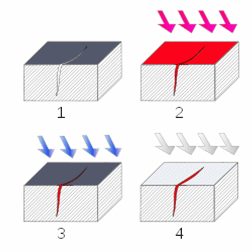
Figure 5.1: Dye penetration test Steps[3]
Chapter 6
Magnetic Particle inspection
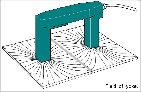
Magnetic particle inspection processes are non-destructive methods for the detection of sur- face and sub-surface defects in ferrous materials. They make use of an externally applied magnetic field through the material, and the principle that the magnetic flux will leave the part at the area of the flaw. The presence of a surface or near surface flaw (void) in the material causes distortion in the magnetic flux through it, which in turn causes leakage of the magnetic fields at the flaw. This deformation of the magnetic field is not limited to the immediate locality of the defect but extends for a considerable distance; even through the surface and into the air if the magnetism is intense enough. Thus the size of the distortion is much larger than that of the defect and is made visible at the surface of the part by means of the tiny particles that are attracted to the leakage fields. The most common method of magnetic particle inspection uses finely divided iron or magnetic iron oxide particles, held in suspension in a suitable liquid (often kerosene). This fluid is referred to as carrier. The particles are often colored and usually coated with fluorescent dyes that are made visible with a hand-held ultraviolet (UV) light (sometimes referred to as black light). The suspen- sion is sprayed or painted over the magnetized specimen during magnetization with a direct current or with an electromagnet, to localize areas where the magnetic field has protruded from the surface. The magnetic particles are attracted by the surface field in the area of the defect and hold on to the edges of the defect to reveal it as a build up of particles. This inspection can be applied to raw material in a steel mill (billets or slabs), in the early stages of manufacturing (forgings, castings), or most commonly to machined parts before they are put into service. It is also very commonly used for inspecting structural parts (e.g., landing gear) that have been in-service for some time to find fatigue cracks. Usually tested pieces needs to be demagnetized before use. Parts are demagnetized by applying AC current through the part and reducing the current which scrambles the magnetic domains causing it to demagnetize. It is a quite economic non-destructive test because it is easy to do and much faster than ultrasonic testing and radiographic testing. Because of the left hand rule, there are two different ways of magnetizing a part, Longitudinal and Circular magnetization. Lon- gitudinal Magnetization passes current through a coil and the magnetic flux lines go through the part. Circular magnetization passes current through the part and establishes a magnetic field around the part. The two different methods are used because cracks can only be seen 45 to 90 degrees to the magnetic flux lines. Magnetic Particle Inspection cannot be used for non-ferrous materials and non-magnetic ferrous materials such as austenitic stainless steels. In such cases, other methods such as dye penetrant inspection are used[4].
Magnetic Flux Leckage(MFL)
It is a magnetic method of nondestructive testing that is used to detect corrosion and pitting in steel structures, most commonly pipelines and storage tanks. The basic principle is that a powerful magnet is used to magnetize the steel. At areas where there is corrosion or missing metal, the magnetic field ”leaks” from the steel. In an MFL tool, a magnetic detector is placed between the poles of the magnet to detect the leakage field. Analysts interpret the chart recording of the leakage field to identify damaged areas and hopefully to estimate the depth of metal loss. This method is best suitable for pipeline examination and tank floors.
Procedure
Typically, an MFL tool consists of two or more bodies. One body is the magnetizer with the magnets and sensors and the other bodies contain the electronics and batteries. The magnetizer body houses the sensors that are located between powerful ”rare-earth” magnets. The magnets are mounted between the brushes and tool body to create a magnetic circuit along with the pipe wall. As the tool travels along the pipe, the sensors detect interruptions in the magnetic circuit. Interruptions are typically caused by metal loss and which in most cases is corrosion. Mechanical damage such as shovel gouges can also be detected. The metal loss in a magnetic circuit is analogous to a rock in a stream. Magnetism needs metal to flow and in the absence of it, the flow of magnetism will go around, over or under to maintain its relative path from one magnet to another, similar to the flow of water around a rock in a stream. The sensors detect the changes in the magnetic field in the three directions (axial ,radial, or circumferential) to characterize the anomaly. An MFL tool can take sensor readings based on either the distance the tool travels or on increments of time. The second body is called an Electronics Can. This section can be split into a number of bodies depending on the size of the tool. This can, as the name suggests, contains the electronics or ”brains” of the instrument. The Electronics Can also contains the batteries and is some cases an IMU (Inertial Measurement Unit) to tie location information to GPS coordinates.
Features
Although primarily used to detect corrosion, MFL tools can also be used to detect features that they were not originally designed to identify. When an MFL tool encounters a geometric deformity such as a dent, wrinkle or buckle, a very distinct signal is created due to the plastic deformation of the pipe wall.
Corrosion
High-resolution MFL tools collect data approximately every 2 mm along the axis of a pipe and this superior resolution allows for a comprehensive analysis of collected signals. Pipeline Integrity Management programs have specific intervals for inspecting pipeline segments.By employing high-resolution MFL tools an exceptional corrosion growth analysis can be con- ducted. This type of analysis proves extremely useful in forecasting the inspection intervals.
Crack detection
There are cases where large non-axial oriented cracks have been found in a pipeline that was inspected by a magnetic flux leakage tool. To an experienced MFL data analyst, a dent is easily recognizable by trademark ”horseshoe” signal in the radial component of the vector field. What is not easily identifiable to an MFL tool is the signature that a crack leaves[4].
Chapter 7 ElectroMagnetic testing
Electromagnetic Testing (ET), as a form of nondestructive testing, in which the process of inducing electric currents or magnetic fields or both inside a test object and observing the electromagnetic response. If the test is set up properly, a defect inside the test object creates a measurable response. The term ”Electromagnetic Testing” is often intended to mean simply Eddy-Current Testing (ECT). However with an expanding number of electromagnetic and magnetic test methods, ”Electromagnetic Testing” is more often used to mean the whole class of electromagnetic test methods, of which Eddy-Current Testing is just one.Common Methods of Electromagnetic Testing are:
Eddy current testing
Eddy-curren testing uses electromagnetic induction to detect flaw in conductive materials. It is used to detect near-surface cracks and corrosion in metallic objects such as tubes and air- craft fuselage and structures. ECT is more commonly applied to nonferromagnetic materials, since in ferromagnetic materials the depth of penetration is relatively small[3].
Procedure
In a standard eddy current testing a circular coil carrying current is placed proximity to the test specimen (electrically conductive).The alternating current in the coil generates changing magnetic field which interacts with test specimen and generates eddy current. Variations in the phase and magnitude of these eddy currents can be monitored using a second ’search’ coil, or by measuring changes to the current flowing in the primary ’excitation’ coil. Variations in the electrical conductivity or magnetic permeability of the test object, or the presence of any flaws, will cause a change in eddy current flow and a corresponding change in the phase and amplitude of the measured current. This is the basis of standard (flat coil) eddy current inspection, the most widely used eddy current technique. However, eddy-current testing can detect very small cracks in or near the surface of the material, the surfaces need minimal preparation, and physically complex geometries can be investigated. The testing devices are portable, provide immediate feedback, and do not need to contact the item.
Limitations
Only conductive materials can be tested, the surface of the material must be accessible, the finish of the material may cause bad readings, the depth of penetration into the material is limited, and flaws that lie parallel to the probe may be undetectable.
Remote field testing (RFT)
It is an electromagnetic method of nondestructive testing whose main application is finding defects in steel pipes and tubes. RFT may also referred to as RFEC (remote field eddy current) or RFET (remote field electromagnetic technique). An RFT probe is moved down the inside of a pipe and is able to detect inside and outside defects with approximately equal sensitivity (although it can not discriminate between the two). Although RFT works in nonferromagnetic materials such as copper and brass, its sister technology eddy-current testing is more effective in these materials.
Procedure
The basic RFT probe consists of an exciter coil (also known as a transmit or send coil) which sends a signal to the detector (or receive coil). The exciter coil is pumped with an AC current and emits a magnetic field. The field travels outwards from the exciter coil, through the pipe wall, and along the pipe. The detector is placed inside the pipe two to three pipe diameters away from the exciter and detects the magnetic field that has traveled back in from the outside of the pipe wall (for a total of two through-wall transits). In areas of metal loss, the field arrives at the detector with a faster travel time (greater phase) and greater signal strength (amplitude) due to the reduced path through the steel. Hence the dominant mechanism of RFT is through-transmission.
Benefits
commonly applied to examination of boilers, heat exchangers, cast iron pipes, and pipelines. No need for direct contact with the pipe wall. Probe travel speed around 30 cm/s (1 foot per second), usually slower in pipes greater than 3 inch diameter.
Limitations
Less sensitive to probe wobble than conventional eddy current testing (its sister technology for nonferromagnetic materials). Because the field travels on the outside of the pipe, RFT shows reduced accuracy and sensitivity at conductive and magnetic objects on or near the outside of the pipe, such as attachments or tube support plates. Two coils generally create two signals from one small defect – a headache for the analyst.
19
Differences Between RFT and ECT
The main differences between RFT and conventional eddy-current testing (ECT) is in the coil-to-coil spacing. The RFT probe has widely spaced coils to pick up the through- transmission field. The typical ECT probe has coils or coil sets that create a field and measure the response within a small area, close to the object being tested.
Alternating Current Field Measurement (ACFM)
It is similar to eddy current applied to steel. Its most common application is to detect and size cracks in welds. The ACFM probe induces a uniform alternating current in the area under test and detects the resulting current flow near to the surface. This current is undisturbed if the area is defect free. A crack redirects the current around the ends and faces of the crack. The ACFM instrument measures these disturbances in the field and uses mathematical modeling to estimate crack size[4].
Benefits
Detects and sizes cracks both length and depth. Can inspect any electrically conductive material. Data recorded electronically for off-line evaluation if necessary. Permanent record of indications. Non-Invasive, inspection without removing any protective coating. Works with surface temperatures up to 500 degrees Celsius.
Limitations
Not recommended for short sections or small items. Locations of weld repairs and localized grinding can cause spurious indications. Crack length needs to be longer than 5 mm. Multiple defects reduce the ability to estimate defect depth. Equipment more bulky than for MT and indications may be more difficult to interpret.
Pulsed eddy current method
A method for the detection and the characterization of corrosion in multi-layer metallic structures. For this technique, a coil (or coils) is used both as field source (driven by a square wave voltage-controlled excitation), and/or as field sensor (measuring a transient response). The field sensor allows the capture of information about the condition of the area of the structure under inspection. The ability of this technique to detect corrosion hinges on the use of a transient response feature (i.e., Lift-off Point of Intersection) to infer the presence of material loss.
Chapter 8 Radiographic Testing
Radiographic Testing (RT), or industrial radiography, is a nondestructive testing (NDT) method of inspecting materials for hidden flaws by using the ability of short wavelength electromagnetic radiation (high energy photons) to penetrate various materials. Since the amount of radiation emerging from the opposite side of the material can be detected and measured, variations in this amount (or intensity) of radiation are used to determine thickness or composition of material. Penetrating radiations are those restricted to that part of the electromagnetic spectrum of wavelength less than about 10 nanometers. The extra feature of these methods is films of the objects being tested can be produced.
X-ray Method
In this method x rays of high frequency are used for inspection.The instrument is as shown in the Fig. 8.1.
Benefits
Metals, nonmetals, composites and mixed materials can be tested. Used on all shapes and forms; castings, welds, electronic assemblies, aerospace, marine and automotive components.
Limitations
Access to both sides of test piece needed. Voltage, focal spot size and exposure time crit- ical radiation hazards. cracks must be oriented parallel to beam for detection. sensitivity decreases with increasing thickness[8].
Gamma Ray method
In this method Gamma rays emitted from radio active source are used for inspection.
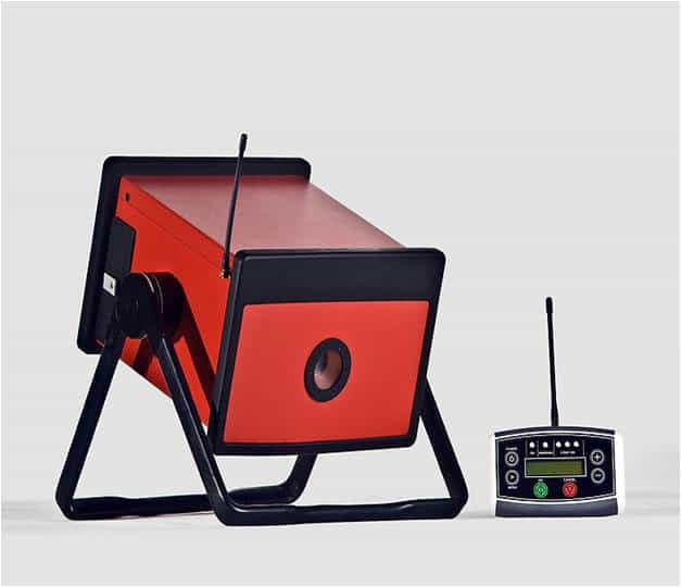
Figure 8.1: X-Ray Equipment[8]
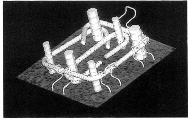
Figure 8.2: X-Ray image of reinforced concrete column[9]
Benefits
Usually used on dense or thick material. Used on all shapes and forms; castings, welds, electronic assemblies, aerospace, marine and automotive components. Used where thickness or access limits X-ray generators.
Limitations
There some radiation chances of hazards. Cracks must be oriented parallel to beam for detection. Sensitivity decreases with increasing thickness. Access to both sides of test piece needed. Not as sensitive as X-rays[8].
Chapter 9 Miscellaneous methods
Visual inspection method
This system consists of stretch pole, which can turn and horizontal arm that can stretch from 1.5m to 3m, and this horizontal arm has high sensitive camera equipment for the inspection on the arm tip.The cameras record the data while traveling.Blind spots(supports) can be easily checked by this method.Best suitable for pipelines and railway tracks[8].
LASER Testing
Laser, stands for Light Amplification by Stimulated Emission of Radiation. It is a device that emits light (electromagnetic radiation) through a process called stimulated emission. Laser’s have applications like
The application of laser are (laser induced breakdown spectroscopy (LIBS)) to deter- mine the composition of building materials.
- we can use lasers for cutting metals and measuring distances.
Infrared and Thermal Testing
Infrared Thermography is the science of measuring and mapping surface temperatures. An infrared thermographic scanning system can measure and view temperature patterns based upon temperature differences as small as a few hundredths of a degree Celsius. Infrared thermographic testing may be performed during day or night, depending on environmental conditions and the desired results.Infrared thermography, a nondestructive, remote sensing technique, has proved to be an effective, convenient, and economical method of testing concrete. It can detect internal voids, delaminations, and cracks in concrete structures such as bridge decks, highway pavements, garage floors, parking lot pavements, and building walls. As a testing technique, some of its most important qualities are that (1) it is accurate; (2) it is repeatable; (3) it doesn’t cause any inconvenience to the public; and (4) it is economical.
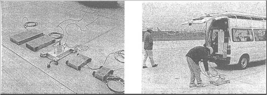
Figure 9.1: Carrying of RADAR Test on pavement[5]
Schmidt hammer
In this the test hammer hits the concrete with a spring-driven pin at a defined energy, and then measures the rebound (in rebound units). Its rebound is dependent on the hardness of the concrete and is measured by test equipment. When conducting the test the hammer should be held perpendicular to the surface which in turn should be flat and smooth. Note that the Schmidt hammer does not work well for small samples and will make marks. By reference to the conversion tables, the rebound value can be used to determine the compres- sive strength. Schmidt hammers are available from their original manfacturers in several different energy ranges[9].
RADAR Technology
The RADAR technology based on Electromagnetic waves has been used not only in ar- chaeology but also in civil engineering. Suitable frequency for carrying experiment must be chosen based on the site conditions, materials involved e.t.c. Example: EM wave tomog- raphy of underground, locating the life lines buried at underground as gas or water pipes, finding air pockets under roads, etc. Moreover, radar system installed on the shield machine which excavates a tunnel at urban area and the system is utilized to find the life lines as gas or water pipes and the metal or woody old piles existing ahead of the machine.Radar is not much influenced by weather, and it is used for void inspection for tunnels and road pavement. Therefore, radar is considered as the most suitable method for inspecting voids under pavement at airports. The Fig.9.1 shows the application of RADAR technology to pavments.
Chapter 10
Case Study: Bridge
Nondestructive testing can be an effective tool in the inspection and condition assessment of bridge structures. It can provide knowledge that may not be possible to deduce from visual observation alone. The integration of both visual and nondestructive inspection methods is key to complete bridge condition assessment and management. Some simple nondestructive techniques, such as hammer sounding, rebound hammer testing, dye penetration, and mag- netic particle testing, can be easily integrated into visual inspections. The results of these integrated inspections will improve bridge data files, and will yield more technically based recommendations for further inspection and maintenance, and more accurate estimations of remaining service life. Once a full representation of the overall bridge condition is determined, appropriate and economical decisions regarding the possible rehabilitation or replacement of bridge members or the entire structure can be made[9]. In the case of concrete bridge the decks consist of a concrete slab covered by an asphalt coating. The concrete slabs generally have a thickness of approximately 25 cm and contain two mats of steel rebar reinforcements. The most serious form of deterioration in concrete bridge decks is the corrosion of steel re- bars caused by the excessive use of chloride deicing salts during winter for the maintenance of the structures. As the reinforcement steel corrodes, it expands and creates a cracks or surface fracture plane in the concrete at, or just above, the level of the reinforcement. The fracture plane, or delamination, may be localized or may extend over a substantial area. Recent advances in NDE techniques have improved the functional characteristics of many NDE methods and have led to systems that are more reliable. Increased use of NDE meth- ods will depend on several factors including the ability of the systems to accurately detect deteriorated conditions, the ease of use and field portability of the systems, and the total cost of completing the NDE based inspections. Since bridges are build in almost hundreds of different kind of types and using so many different materials of supporting components, so that it is not possible to use just one NDT method for all tasks. For instants, microwave or ground penetrating radar (GPR) may be used for reinforced concrete decks but is not suitable for weld testing of steel members. Also there are many tasks which need further research to make NDT methods suitable. A lot of application reports of NDT methods for bridge testing are there. Several methods are available, some are in research and some are used for further inspection after regularly inspections indicates their needs[7].
They include:
- Impact-Echo (IE) for checking integrity of concrete[9].
- Impact-Echo (IE) is suitable to determine the thickness of the concrete[9].
Magnetic flux leakage (MFL) to detect corrosion in strands and bars in post-tensioned concrete structures[].
The nuclear magnetic resonance (NMR) method can determine the presence and loca- tion of water. This enables the determination of pore size and pore distribution as the concrete cures.
- Infrared imaging technologies to find defects in the concrete parts of bridges..
- Strain Transducers to record the induced strains.
Potential mapping is the most simple electrochemical technique used for obtaining corrosion information on site. The technique informs qualitatively on the corrosion risk of the reinforcement in the reinforced concrete structures.
Acoustic emission monitoring can play a very effective role in enhancing safety, ensuring availability and reducing the repair/refurbishment costs of bridges.
A well-established and accepted application of GPR is the accurate condition assess- ment of bridge decks as well as other reinforced concrete structures. The ability of GPR to be used without requiring the removal of an existing asphalt.
Ultrasonic testing allows also the visualization of perpendicularly arranged reinforce- ment bars, tendon ducts. UT can compensate deficits of the radar method[4].
The combined application of radar, impact-echo and ultrasonic echo for the assessment of post-tensioned concrete structures[5].
Liquid-penetration testing – Visual check of dye that penetrates hairline fractures in pavement.
- Ultrasonic testing of welds, bolts and rivets steel members.
- Divers inspect underwater concrete piers, which may have been damaged by erosion.
- Magneto-inductive is used for evaluation of cables and wires.
Laser Measurement Technologies for numerous applications using laser-based distance measurements for highway infrastructure. Applications for this technology include measuring bridge deflections under calibrated load to evaluate structural behavior, calculating out-of-plane distortions in girder webs and flanges, and evaluating the as- built construction of large structures such as abutments.
Bridge Monitoring Systems using acoustic emission sensors or eddy-current sensor. Generally, these instruments are dedicated, remote data-acquisition systems that col- lect information on the behavior of a structure over time. The acoustic emissions detection system can evaluate sounds emanating from any materials, including steel cables, trusses and concrete in a bridge. Cracks can be recognized many months before they are visible on the surface.
- Thermographic methods for evaluating composite bridges and composite bridge repairs.
Both ultrasonic and radiographic testing are used to inspect steel bridges during fab- rication to ensure weld quality.
Automated Ultrasonic Testing (AUT) can be an effective inspection tool that could be used in place of radiography under certain conditions.
Ultrasonic velocity measurements can be used as a quality-control tool during con- struction and how ultrasonic testing may be used for in-service inspection of bridges constructed of reactive powder concrete (RPC).
- Electromagnetic acoustic transducers could detect broken wires within a strand.
Electrochemical Fatigue Sensor (EFS) can be used to determine if actively growing fatigue cracks are present. An EFS sensor is first applied to the fatigue sensitive location on the bridge or metal structure, and then is injected with an electrolyte at which point a small voltage is applied. An algorithm automatically indicates the level of fatigue crack activity at the inspection location.
Brillouin fiber optic sensor technology is a promising technology for structural health monitoring (SHM) thanks to its unique feature of distributed strain and temperature measurement by means of low-cost optical fibers.
X-ray computed tomography for determination of crack propagation in concrete us- ing[8].
X-ray computed tomography for determination of void percentage and distribution in concrete.
Prompt Gamma Neutron Activation Analysis for determination of chloride concentra- tion and depth profiles in concrete.
- Neutron scattering technique measuring cement hydration using.
Ultrasonic method for direct measurement of preload force of bolted connections. This is an innovative technique for direct measurement of actual bolt stresses
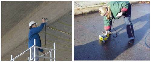
Figure 10.1: Schmidt Hammer[7],GPR Test being conducted on a bridge[5]

Figure 10.2: Figure showing the RADAR data[5]
Robotic Tacheometry System (RTS) (Total Station) offers the capability to measure the spatial coordinates of discrete points on a bridge without having to touch the structure. There is incredible technology out there to help monitor and diagnose problems, and research continues to develop new technologies to keep up with the infrastructure of bridges. Older bridges need more than just a regular inspection. As bridge get older, it needs more tests[7].
Chapter 11 Conclusions
The present report aimed at explaining the methods of NDT and their techniques. A case study of bridges also studied. Engineering is not always complete, and further research works are needed. To set up a good system for maintenance of existing concrete structures, there are still many things to be done. Different methods can be applied to the same problem, but the best method is choosen based on the features of the problem.
Bibliography
- J H BUNGEY, “Non destructive testing in U K.”,Seiken Symposium,2000.
- www.wikipedia.com, “ Non destructive testing.”, 14 November 2009.
- www.ndt.org, “ Non destructive testing” 14 November 2009.
- Y.H.Cha anb J H shu. “Differential approach to Ultrasonic Testing of Strength and Homogenety of concrete” Seiken symposium.,2000.
- K R Maser and I sande , “Application of Ground Penetration RADAR technique for evaluation of Air field pavment”, Seiken Symposium 2000 .
- N.Tamura and K.Takada, “ High Evaluation Inspection vehicle”, Seiken Symposium,
2000.
- K Brandes,J Herther and R.Helmerich. “ Non – destructive testing being essential part of the safety assesment of steel bridges ” Seiken Symposium 2000.
- J F Hinslay, “text book of Non destructive Testing”.
- A P Ferrerira and P F Castro. “NDT for assessing concrete strength” Seiken sympo- sium.,2000.

