Defect Characterisation in Ultrasonic Testing
Written by: Jim Houf
This article describes common defects found in angle beam UT weld inspections along with examples of the transducer positions and resulting screen presentations related to those defects. Common false indications and the means of determining them are also discussed.
Defect Characterisation in Ultrasonic Testing
The following terms are often used interchangeably and sometimes incorrectly to describe ultrasonic testing signals.
Relevant and Nonrelevant Indications. A signal seen on the UT screen that results from sound reflecting from an internal reflector within the part being inspected or caused by a physical condition such as geometry is called an indication. A relevant indication is created by a physical reflector in the part. A nonrelevant indication is caused by part geometry or a physical condition other than an actual discontinuity or defect.
Discontinuity. A discontinuity is any foreign material in the part (slag, porosity, etc.) or an unintended disruption in the weld or base material such as a crack, incomplete penetration or incomplete fusion. If the discontinuity type and size are within the acceptable limits of the criteria of the governing documents, they may be acceptable. Small amounts of slag or porosity may be acceptable depending on their size. However, certain discontinuity types (cracks, incomplete penetration or lack of fusion) are often rejectable regardless of size.
Defect. A discontinuity that is rejectable is a defect. To determine that a discontinuity is indeed a defect according to the criteria of the governing code or specification, the UT operator must first know the type of discontinuity causing the indication, accurately locate it with respect to a known reference point on the weld, and determine its size.
Cracks
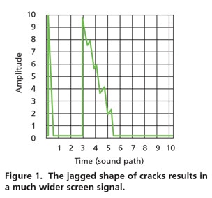
Cracks are usually linear and irregular or jagged. In normal indications, the damping in the transducer causes the right side of the signal to drop off quickly. However, because a crack is jagged, multiple returns result, causing the screen signal to be much wider thus producing a distinctive indication on the UT screen referred to as a “church steeple” (Fig. 1).
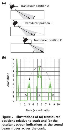
Another effective way to determine that an indication is a crack is in the way in which a crack indication “walks” across the screen (Fig. 2). As the sound beam begins to move across the crack, the inherent beam spread causes the leading edge of the sound cone to reflect sound back well before the signal is maximized. This causes a short or low amplitude signal to appear on the far right side of the screen (signal A).
As the transducer gets closer to the crack, more of the sound beam reflects back causing the signal height to increase and move toward the left side of the screen as the sound path gets shorter. When the centerline of the sound beam, where the sound strength is greatest, reaches the base of the crack, the signal is usually at maximum strength (signal B).
As the centerline clears the crack and the trailing edge moves past the crack, the signal height drops and it moves toward the left of the screen until it disappears (signal C). In effect, we see a wide short signal that grows in height as it moves towards the left and then diminishes in height until it disappears.
If the width of the UT screen is set at one full skip distance, the crack should start to appear just to the right of the midpoint and then drop off the screen near the quarter point of the screen between the main bang and the midpoint (Fig. 2). If the crack starts from the scanning surface, the signal should walk in from the far right of the screen and drop off just to the right of the midpoint.
These are generalizations and the exact location will depend on the material thickness and will vary due to the different sound paths. Because of this, it is possible for the operator to overlook a shallow same-side crack in the first leg if the signal is so close to the scanning surface that it appears to be part of the main bang.
Incomplete Penetration
An incomplete penetration (IP) signal tends to behave much like the signal for a crack, traveling from right to left on the screen; increasing and then decreasing in height. However, because IP is generally smooth-sided (the unfused edge of the weld groove) rather than jagged like a crack, the width of the screen signal is generally much narrower than that of a crack signal.
A problem that occurs frequently is that since the IP is at the root of the weld, the screen signal may not have been fully maximized when the transducer hits the near edge of the weld crown. In thinner materials, this problem is likely to occur. Scanning from both sides of the weld may not catch this configuration.
If the signal continues to increase in height until the transducer hits the weld crown, it may be that the signal, which has not reached rejectable size, is indeed rejectable. If this occurs, a smaller transducer may be needed to get close enough to fully maximize the signal. Failure to do so may cause an operator to accept a rejectable defect.
Sidewall Lack of Fusion
Sidewall lack of fusion (LOF)is a particularly hard defect to identify. Common bevel angles in weld joints do not often complement the angles used for ultrasonic testing. As a result, the orientation of the unfused sidewall of the weld may not return a signal amplitude large enough to be rejectable. Additionally, sidewall LOF may not show at all in the first leg when the weld is scanned from the side where the defect is located, or may show as an acceptable indication when seen in the second leg.
Thus, the weld must be inspected from both sides when the part configuration permits. If signals occur that are determined to be along the side of the weld, even if they do appear acceptable, it may be necessary to switch wedge angles and interrogate the area again to determine whether or not sidewall LOF is present.
Slag
During the welding process, powdered or granular flux is melted to provide shielding gasses for the welding arc. As the residue cools, the solids form a glasslike substance called slag which may be trapped in the weld creating a slag inclusion. An overall irregular shape is a clue that a slag inclusion is the indication being seen.
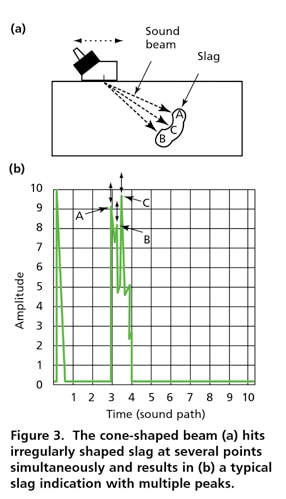
Because the cone-shaped sound beam hits the irregularly shaped slag at several points at once, the signal tends to give a presentation with multiple peaks (Fig. 3). As the transducer moves forward, the centerline of the beam hits the various contours with more strength, causing the height or amplitude of each signal to increase and then drop off as the sound beam crosses each reflection point.
As a result, the multiple peaks of the signal will go up and down as well as move slightly to the right or left as the scan progresses. This signal with multiple peaks alternating up and down is typical of slag inclusions. The alternating peaks can be effectively demonstrated by stopping the transducer when a multipeak signal is maximized then angulating the transducer back and forth sideways at that position.

Porosity
Weld porosity forms in a manner similar to slag, when gas is trapped in the cooling weld metal before it can escape to the surface of the weld. However, rather than having solids in the inclusion and being irregularly shaped, pores are usually gas-filled and rounded in shape.
Reflectors. A flat (planar) surface perpendicular to the sound beam will reflect a large amount of sound resulting in a very high screen signal. A side-drilled hole is a line reflector, reflecting sound from the circumference only where the sound beam strikes the hole perpendicular to the circumference with a length equal to the depth of the hole. As a result, the signal from a side-drilled hole is smaller in screen amplitude (height) than a planar reflector.
A rounded reflector, such as a gas pore, is a point source and sound only reflects from it at a single point where the sound beam strikes the hole perpendicular to the circumference. Because a pore has no appreciable length and the diameter is usually a very small percentage of the cross-sectional area of the sound beam, the signal from a pore returns a very small amount of sound, resulting in a very discrete screen signal often of low amplitude. The effect of the sound beam reflecting from that circular shape gives the screen signal for porosities distinctive characteristics.
When the sound beam first hits a circular pore, it does so at a slight angle, causing the sound to reflect away from the transducer (Fig. 4a). As the centerline of the sound beam hits the pore directly, sound is reflected back to the transducer (Fig. 4b).
However, as the centerline passes over the pore, sound in the lower portion of the sound cone is again reflected away from the transducer (Fig. 4c). The overall result is a single, narrow, sharp signal that pops up on the screen at only one location and then disappears immediately. There are some exceptions to this; if the pore is large or is close to the scanning surface, the signal may move slightly to the left, usually 1 to 2 minor graticules, before disappearing.
Again, the pore is a point source and once the signal is maximized, the operator will notice that a slight movement of the transducer forward or backward, or oscillation of the transducer slightly to the right or left, will cause the signal to disappear.
In the case of cluster porosity or closely aligned pores, the screen display may demonstrate several signals very close together that can be confused with a slag inclusion. However, it is often possible to isolate the individual signals, which will show the very tight or narrow trace and the location of each signal at one spot without significant lateral movement, which generally does not occur with a slag inclusion.
Nonrelevant and False Indications
As mentioned earlier, nonrelevant indications are those that will not affect the use of the part or are created by geometry or other physical characteristics. Some of the more common indications in this category are backing bar indications, mode conversion and signals from sources outside of the weld.
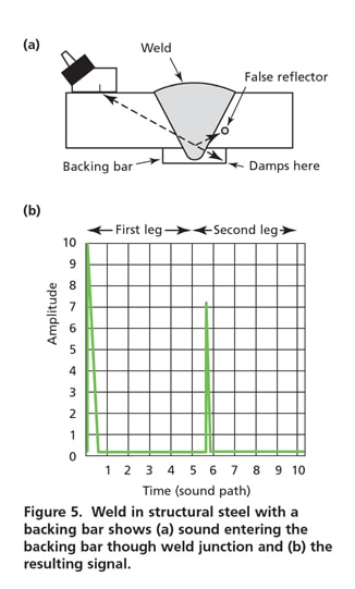
Backing Bars. Backing bars are commonly used in butt welds on structural steel. Their purpose is to provide a surface under the weld groove on which to lay the first bead or root pass of the weld. A properly welded backed butt joint will result in full penetration between the sidewalls of the weld and the backing bar.
As a result, sound may enter the backing bar through this weld junction, ricochet around in the backing bar, reflect from one of the corners and then return back to the transducer. Figure 5a shows this joint configuration and how the sound beam may reflect back from a corner.
The signal from the backing bar reflector shown will appear just a bit into the second leg and may be misidentified as a sidewall discontinuity because of the apparent location of the signal on the screen (Fig. 5b). If the backing bar is accessible, this type of false indication can usually be damped with a finger wet with couplant as shown.
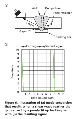
Mode Conversion. Mode conversion results when a shear wave reflects from a surface that causes the wave to convert to a longitudinal wave. This occurs occasionally on backed welds when the shear wave hits the gap created by a poorly fit up backing bar, converts to a longitudinal wave and travels up to the weld crown (Fig. 6).
The L-wave then returns to the root, converts back to a shear wave and returns to the transducer. Because the L-wave velocity is approximately twice that of a shear wave, the resulting signal appears about halfway out in the second leg. The weld crown is a good reflector and the signal is very strong, often exceeding 100 percent of full screen height.
The location and height of the mode conversion signal easily identify this type of false indication. First, the height of the signal is extremely strong for a discontinuity at the apparent location. Secondly, if the sound path is calculated correctly, the operator can see that the apparent location is outside of the weld and heat-affected zone.
When this occurs, damping the surface of the weld with a wet finger shows that the sound has converted and can be damped on the weld crown. Mode conversion like this can also occur in open root pipe welds and double V plate welds if the root or opposite side weld crowns are a shape that permit it.
Extraneous Reflectors
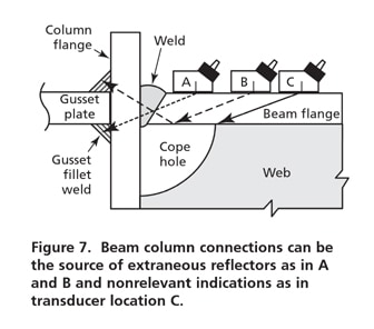
Occasionally, screen signals show up where no signal should logically be. An example can be shown in beam-column connections. If a gusset plate has been welded between the column flanges to carry the structural load across the column and the plate is in line with the upper and lower beam flanges, the gusset fillet welds may reflect sound back to the transducer as shown in transducer positions A and B in Fig. 7. These signals can be confusing because they appear to be outside the weld area. When these occur, it is necessary to visually inspect the part to see if another part or weld may be causing the errant signal.
Another nonrelevant indication may occur in beam-column connections if cope holes have been cut in the web to permit access to the full width of the beam flange. This signal usually appears strong in the first leg when the transducer is near the center of the beam (over the web) but is too far away from the weld to be a relevant indication as in transducer position C in Fig. 7. If this occurs, the operator should wet a finger with couplant and damp along the edges of the cope hole to confirm that the signal is coming from the hole.
It should be noted that the discontinuity descriptions discussed in this article are general in nature and the actual discontinuities in production welds may vary depending on wedge angle, material thickness, weld configuration and discontinuity size. However, if operators are familiar with the general screen presentations for different discontinuity types, they are better equipped to categorize a weld defect or correctly identify false indications that would be costly if misidentified and called out as defects. TNT
*Jim Houf is Senior Manager of ASNT’s Technical Services Department and administers all ASNT certification programs. (800) 222-2768 X212, (614) 274-6899 fax, <jhouf@asnt.org>.
Visit our Ultrasonic Testing Group.


Responses