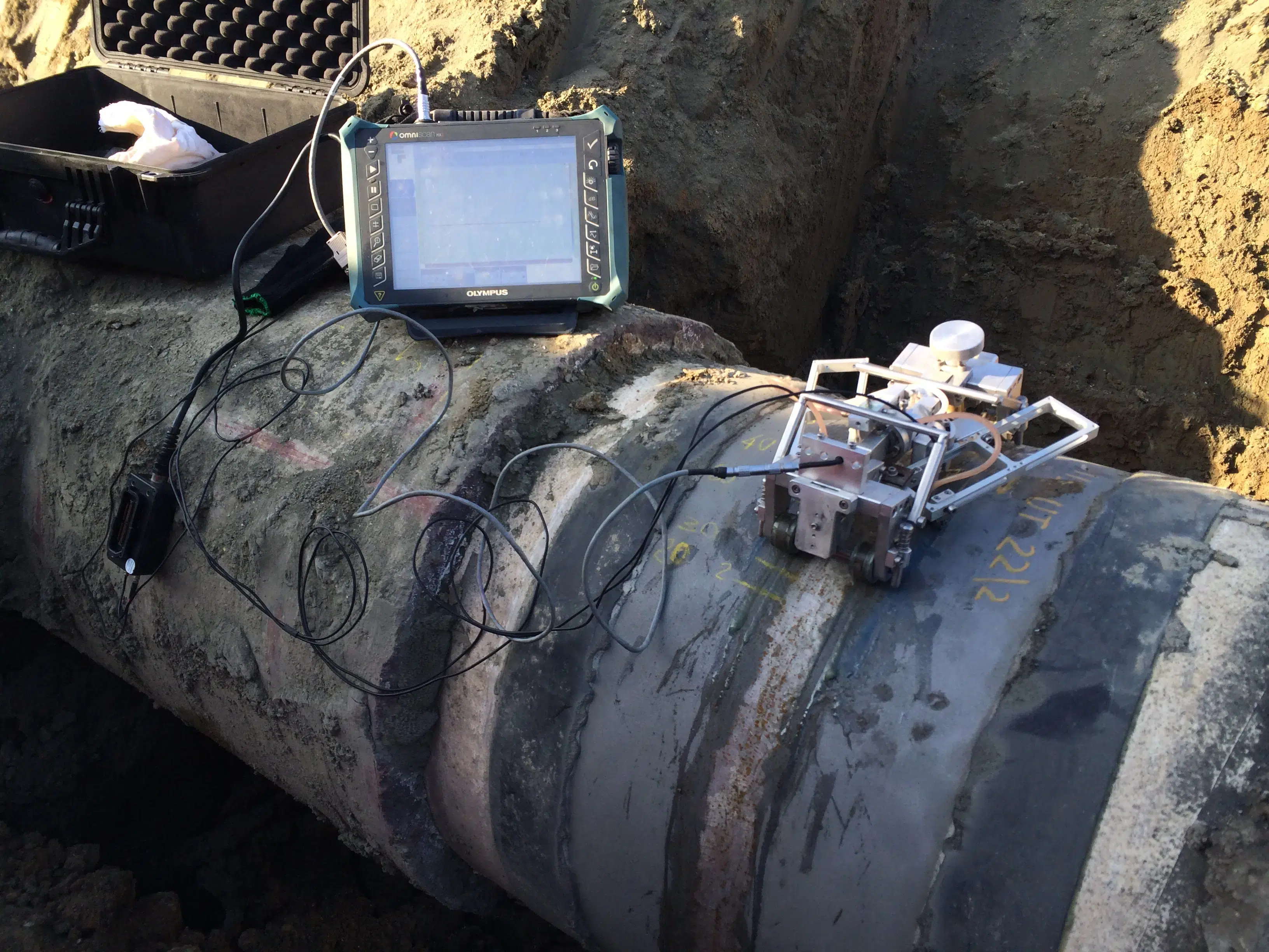
Pipeline Inspection
Public Pipeline
Active 2 weeks ago
Welcome to [NDT Inspection Portal]’s pipeline inspection group, a place for professionals to connect... View more
Public Pipeline
Group Description
Welcome to [NDT Inspection Portal]’s pipeline inspection group, a place for professionals to connect and discuss the latest techniques and technologies in pipeline inspection.
Pipeline inspection is a critical aspect of ensuring the integrity and reliability of pipelines in various industries, including oil and gas, water and wastewater, and transportation. It involves the use of specialized equipment and techniques, including non-destructive testing (NDT) methods, to evaluate the condition and performance of pipelines and identify any potential issues or defects.
Pipeline inspection is an important aspect of ensuring the safety and reliability of pipelines and is often required by regulatory agencies to ensure compliance with safety standards. It involves the use of various methods and techniques, including ultrasonic testing, radiographic testing, and magnetic particle inspection, to evaluate the condition of pipelines and identify any issues or defects.
Our member group offers a platform for sharing knowledge and best practices on pipeline inspection and its applications in various industries. Join our community of experts from around the world and be a part of the conversation on advancing the practice of pipeline inspection and its applications in the field of NDT and inspection. Whether you are new to pipeline inspection or an experienced professional, you’ll find valuable resources and a welcoming community in our group.
Reply To: Hi-Low or misalignment in pipes
-
watch scans Left ( L) and Rigth (R) side .
G1 , G2, G3 are the geometries ( G ) ; d1, d2 , d3 , d4 are defects LOF type ( d ). Part of these defects coexist with a geometry : d1 with G1, G2 with d3 , G3 with D4 . The observation point is the discriminating factor between defect and geometry , so the scanning position R-d4 (scan right pointing d4) shows the defect d4 , L-G3 (scan Left pointing G3) shows the G3 geometry. The defect d4 is the continuation of geometry G3 and vice versa, then scan position Rd-4 and L-G3 pointing the same welding area. And so on for the other scans represented.
Because of misalignment root and esternal cap paths are lengthened or shortened compared to a normal joint. For the same reasons, the projection of the cap root path – normally a few millimeters beyond the CL – will be in C.L. position.The signature of this situation is the absence of any signal in the root scanning position R-d2: if there is a signal generated this signal is unequivocally defect d2.
Scanning with straight beam probe – often underestimated – provides additional information on the status of the root. In case of a joint regularly aligned and penetrated (P-Scan), we have the rapid sequence with 3 signals 10-12-10 path. If the joint is not penetrated ( IP-Scan ) the paths become 10 – 8-10 (reduction of thickness at the center, instead of increase), with the same dynamic. In the case of misalignment ( M-scan) path reduce at first sight similar to IP-scan, but the dynamic is different: after a rapid change from the path from 10 to 8,will follow a phase of slow variation of the thickness, without the dynamic net of a third signal as observed in IP-scan.
The evaluation of misalignment normally is done not with UT examination bat with visual/dimensional inspection according to the construction requirements.
Greetings