Ultrasonic Testing (UT) Calculations
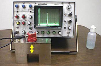
Ultrasonic testing (UT) is a non-destructive testing method that uses high frequency sound waves to inspect materials for defects. The following are some of the key calculations used in ultrasonic testing:
Wavelength Calculation:
The wavelength of an ultrasonic wave is calculated using the formula:
Wavelength (λ) = Velocity of sound (c) / Frequency (f)
where c is the velocity of sound in the material being tested and f is the frequency of the ultrasonic wave.
Example:
Let’s say we have an ultrasonic transducer that operates at a frequency of 2 MHz (2 million cycles per second). To calculate the wavelength of the ultrasonic wave in steel, we can use the following formula:
Wavelength (λ) = Velocity of Sound (c) / Frequency (f)
Where c is the velocity of sound in steel (which is typically around 5900 m/s). Plugging in the values, we get:
Wavelength (λ) = 5900 m/s / 2 MHz = 2950 μm
Time of Flight Calculation:
The time of flight (TOF) of an ultrasonic wave is calculated as the time taken for the wave to travel from the transducer to the reflector and back to the transducer. It can be calculated using the formula:
Time of Flight (TOF) = 2d / c
where d is the distance from the transducer to the reflector.
Example:
We want to determine the time of flight for an ultrasonic wave traveling through steel with a velocity of 5900 m/s. The distance to the reflector is known to be 10 millimeters. To calculate the time of flight, we can use the following formula:
Time of Flight (TOF) = 2 * Distance (d) / Velocity of Sound (c)
Time of Flight (TOF) = 2 * 10 mm / 5900 m/s = 0.00338 seconds
So in this example, the time of flight for the ultrasonic wave is 0.00338 seconds, or 3.38 microseconds.
Distance Calculation:
The distance from the transducer to the reflector can be calculated using the formula:
Distance (d) = TOF (t) * Velocity of sound (c) / 2
Example:
An ultrasonic pulse with a velocity of 5900 m/s in steel and a time of flight of 20 microseconds. To calculate the distance to a reflector, we can use the following formula:
Distance (d) = Velocity of Sound (c) * Time of Flight (TOF) / 2
Distance (d) = 5900 m/s * 20 μs / 2 = 59000 μm
So in this example, the distance to the reflector is 59000 micrometers, or 59 millimeters.
Pulse-Echo Calculation:
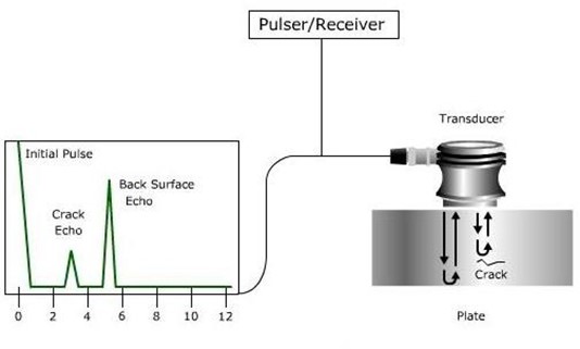
The pulse-echo method is used to determine the distance to a reflector or the thickness of a material. The pulse-echo time is calculated as the time between the transmitted pulse and the received echo. The distance to the reflector can be calculated using the formula:
Distance (d) = Pulse-Echo Time (t) * Velocity of sound (c) / 2
Example:
An ultrasonic pulse with a velocity of 5900 m/s in steel and a time of flight of 20 microseconds. The reflector is known to be 10 millimeters away. To calculate the total round-trip time for the pulse, we can use the following formula:
Total Round-Trip Time = 2 * Time of Flight (TOF)
First, we’ll calculate the time of flight (TOF) using the following formula:
Time of Flight (TOF) = Distance (d) / Velocity of Sound (c)
We get: Time of Flight (TOF) = 10 mm / 5900 m/s = 0.00169 seconds
So the time of flight is 0.00169 seconds, or 1.69 microseconds.
Next, we’ll use this value to calculate the total round-trip time:
Total Round-Trip Time = 2 * Time of Flight (TOF) = 2 * 1.69 μs = 3.38 μs
So in this example, the total round-trip time for the ultrasonic pulse is 3.38 microseconds.
Through-Transmission Calculation:
The through-transmission method is used to determine the thickness of a material. The thickness of the material can be calculated using the formula:
Thickness (t) = Time of Flight (TOF) * Velocity of sound (c) / 2
Example:
Let’s say we have two ultrasonic transducers, one serving as the sender and the other as the receiver. The distance between the two transducers is known to be 20 millimeters. To calculate the time of flight for the through-transmission, we can use the following formula:
Time of Flight (TOF) = Distance (d) / Velocity of Sound (c)
Where d is the distance between the transducers and c is the velocity of sound in the material being tested (which is typically around 5900 m/s in steel). Plugging in the values, we get:
Time of Flight (TOF) = 20 mm / 5900 m/s = 0.00338 seconds
So in this example, the time of flight for the through-transmission is 0.00338 seconds, or 3.38 microseconds.
Velocity Calculation:
The velocity of sound in a material can be calculated using the formula:
Velocity of sound (c) = Wavelength (λ) * Frequency (f)
Example:
An ultrasonic pulse with a known time of flight of 20 microseconds and a known distance to a reflector of 10 millimeters. To calculate the velocity of sound in the material being tested, we can use the following formula:
Velocity of Sound (c) = Distance (d) / Time of Flight (TOF)
Plugging in the values, we get:
Velocity of Sound (c) = 10 mm / 20 μs = 5900 m/s
So in this example, the velocity of sound in the material being tested is 5900 meters per second. This is a common value for steel, but the velocity of sound can vary depending on the material being tested and its temperature and other conditions.
Reflection Coefficient Calculation:
The reflection coefficient (RC) is a measure of the amount of energy that is reflected at an interface between two materials with different acoustic impedance. It is calculated using the formula:
Reflection Coefficient (RC) = (Z2 – Z1) / (Z2 + Z1)
where Z1 and Z2 are the acoustic impedances of the two materials.
Example:
Let’s say we have an ultrasonic pulse that encounters an interface between two materials with different acoustic impedances. The acoustic impedance of the first material is known to be 400 kg/m^2s and the acoustic impedance of the second material is known to be 1000 kg/m^2s. To calculate the reflection coefficient, we can use the following formula:
Reflection Coefficient (ρ) = (Z2 – Z1) / (Z2 + Z1)
Plugging in the values, we get:
Reflection Coefficient (ρ) = (1000 kg/m^2s – 400 kg/m^2s) / (1000 kg/m^2s + 400 kg/m^2s) = 0.2
So in this example, the reflection coefficient is 0.2, which means 20% of the ultrasonic energy is reflected at the interface and 80% is transmitted. The reflection coefficient can be used to determine the amount of energy reflected from an interface, which can provide information about the material or defect that is causing the reflection.
Sound Path Calculation:
The sound path is the distance traveled by the ultrasonic wave through the material being tested. It can be calculated using the formula:
Sound Path (SP) = Velocity of sound (c) * Pulse-Echo Time (t) / 2
Example:
Let’s say we have an ultrasonic pulse that travels from the sender to a reflector and back to the receiver. The time of flight for the round trip is known to be 20 microseconds. To calculate the sound path, we can use the following formula:
Sound Path (L) = Velocity of Sound (c) * Time of Flight (TOF) / 2
Where c is the velocity of sound in the material being tested (which is typically around 5900 m/s in steel) and TOF is the time of flight for the round trip. Plugging in the values, we get:
Sound Path (L) = 5900 m/s * 20 μs / 2 = 59,000 μm
So in this example, the sound path is 59,000 micrometers, or 59 millimeters. This value represents the distance that the ultrasonic pulse traveled from the sender to the reflector and back to the receiver.
Damping Calculation:
Damping is a measure of the amount of energy that is lost due to friction and other forms of internal loss in a material. It can be calculated using the formula:
Damping = -20 * log10 (Reflection Coefficient (RC))
Example:
An ultrasonic pulse that travels through a material and experiences some energy loss due to material damping. The pulse amplitude at the sender is known to be 1 volt and the pulse amplitude at the receiver is known to be 0.5 volts. To calculate the material damping, we can use the following formula:
Damping (α) = – 20 * log10(A2 / A1)
Where A1 is the amplitude of the pulse at the sender and A2 is the amplitude of the pulse at the receiver. Plugging in the values, we get:
Damping (α) = – 20 * log10(0.5 V / 1 V) = -6 dB
So in this example, the material damping is -6 dB, which means that the pulse amplitude decreased by a factor of 0.5 due to material damping. This value can be used to determine the amount of energy lost due to material damping and can provide information about the material’s properties.
Beam Angle Calculation:
The beam angle is the angle between the direction of the transmitted ultrasonic wave and the normal to the surface of the material being tested. It can be calculated using the formula:
Beam Angle (θ) = 2 * sin^-1 (λ / (2 * d))
where d is the distance from the transducer to the reflector.
Example:
An ultrasonic transducer with a known frequency of 2 MHz and a known wavelength of 0.29 mm. To calculate the beam angle, we can use the following formula:
Beam Angle (Θ) = sin^-1(λ / 2d)
Where λ is the wavelength and d is the diameter of the transducer. Plugging in the values, we get:
Beam Angle (Θ) = sin^-1(0.29 mm / 2 * 20 mm) = 7.6°
So in this example, the beam angle is 7.6 degrees. This value represents the angle at which the ultrasonic energy is spread out from the transducer. A narrower beam angle results in a more focused beam, which can provide better resolution, while a wider beam angle results in a less focused beam, which can cover a larger area.
Pulse Repetition Frequency (PRF) Calculation:
The pulse repetition frequency (PRF) is the number of pulses generated by an ultrasonic transducer in a given time period. It can be calculated using the formula:
PRF = 1 / Pulse Duration (PD)
where Pulse Duration (PD) is the duration of a single pulse in seconds.
Example:
Let’s say we have an ultrasonic testing system that can transmit and receive ultrasonic pulses at a rate of 500 pulses per second. To calculate the Pulse Repetition Frequency (PRF), we can use the following formula:
Pulse Repetition Frequency (PRF) = Pulse Rate (R) / Number of Channels (N)
Where R is the pulse rate and N is the number of channels being used for transmission and reception. For this example, let’s assume we are using 1 channel for both transmission and reception:
Pulse Repetition Frequency (PRF) = 500 pulses/s / 1 channel = 500 Hz
So in this example, the Pulse Repetition Frequency (PRF) is 500 Hz, which represents the rate at which the ultrasonic testing system is transmitting and receiving pulses. The PRF is an important factor in ultrasonic testing as it can affect the quality of the signals being received and the overall accuracy of the measurements.
Pulse Duration Calculation:
The pulse duration is the length of time for which an ultrasonic pulse is transmitted. It can be calculated using the formula:
Pulse Duration (PD) = 1 / Pulse Repetition Frequency (PRF)
Example:
Let’s say we have an ultrasonic pulse with a frequency of 2 MHz and a bandwidth of 200 kHz. To calculate the pulse duration, we can use the following formula:
Pulse Duration (τ) = 1 / (Bandwidth (BW))
Plugging in the values, we get:
Pulse Duration (τ) = 1 / (200 kHz) = 5 µs
So in this example, the pulse duration is 5 µs, which represents the time it takes for the pulse to go from its maximum value to its minimum value. The pulse duration can have a significant effect on the quality of the ultrasonic signals being received and the accuracy of the measurements, so it is an important factor to consider when conducting ultrasonic testing.
Resonant Frequency Calculation:
The resonant frequency is the frequency at which an object or material vibrates with maximum amplitude. It can be calculated using the formula:
Resonant Frequency (f) = 1 / (2 * π * sqrt (m / k))
where m is the mass of the object or material and k is the stiffness.
Example:
Let’s say we have a piezoelectric transducer with a known length of 50 mm and a known velocity of sound in the material of the transducer of 5000 m/s. To calculate the resonant frequency of the transducer, we can use the following formula:
Resonant Frequency (f) = Velocity of Sound (v) / 4 * Length (L)
Plugging in the values, we get:
Resonant Frequency (f) = 5000 m/s / 4 * 50 mm = 5000 / 200 = 25 kHz
So in this example, the resonant frequency of the transducer is 25 kHz, which represents the frequency at which the transducer will produce its maximum output for a given input. The resonant frequency is an important factor in ultrasonic testing as it can affect the quality of the signals being received and the overall accuracy of the measurements. By understanding the resonant frequency of the transducer, it is possible to optimize the testing parameters to achieve the best results.
Attenuation Calculation:
Attenuation is the reduction in the amplitude of an ultrasonic wave as it travels through a material. It can be calculated using the formula:
Attenuation = 20 * log10 (Amplitude1 / Amplitude2)
where Amplitude1 is the initial amplitude and Amplitude2 is the final amplitude after the wave has traveled a distance through the material.
Example:
Let’s say we have an ultrasonic signal with an initial amplitude of 1 volt that travels a distance of 10 cm in a material and is measured to have a final amplitude of 0.5 volts. To calculate the Attenuation, we can use the following formula:
Attenuation = 20 * log10 (1 V / 0.5 V) = 20 * log10 (2) = 20 * 0.301 = 6.02 dB
So in this example, the Attenuation of the ultrasonic signal is 6.02 dB, which represents the reduction in amplitude due to the material’s inherent absorption of the ultrasonic energy. Attenuation is an important factor to consider when conducting ultrasonic testing as it can affect the quality of the signals being received and the overall accuracy of the measurements.
Distance Amplitude Correction (DAC) Curve Calibration:
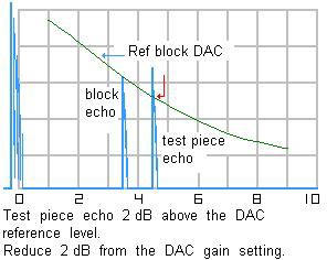
The distance amplitude correction (DAC) curve is a graph that shows the relationship between the amplitude of an ultrasonic echo and the distance it has traveled through the material being tested. This curve is used to correct for the attenuation that occurs as the ultrasonic wave travels through the material. To calibrate the DAC curve, the following formula can be used:
DAC = Amplitude of Echo / (Amplitude of Pulse * cos (Beam Angle))
Example:
Let’s say we have an ultrasonic pulse with an amplitude of 1 volt that is transmitted into a material and returns an echo with an amplitude of 0.5 volts. The beam angle of the ultrasonic probe is 30 degrees. To calculate the DAC in dB, we can use the following formula:
DAC (dB) = 20 * log10 (Amplitude of Echo / (Amplitude of Pulse * cos (Beam Angle)))
Plugging in the values from the example:
DAC (dB) = 20 * log10 (0.5 V / (1 V * cos (30 degrees))) = 20 * log10 (0.5 / (0.8660)) = 20 * log10 (0.5735) = 20 * (-0.2467) = -4.934 dB
So in this example, the DAC correction factor in dB is -4.934 dB. This value represents the correction factor that should be applied to the measurement to compensate for the loss of signal amplitude due to the material’s inherent absorption of ultrasonic energy.
Focal Law Calculation:
The focal law is a mathematical formula that is used to determine the position and intensity of the ultrasound beam in a material. It can be calculated using the formula:
Focal Law = sin (θ) / Velocity of Sound (c) * Pulse-Echo Time (t)
Here’s an example calculation of the Focal Law:
Let’s say that the angle of the probe is θ = 60 degrees, the velocity of sound in the material being tested is c = 5,500 m/s, and the Pulse-Echo Time (t) is 20 microseconds. To calculate the Focal Law, we can plug in these values into the formula:
Focal Law = sin (60 degrees) / (5,500 m/s) * (20 x 10^-6 s) = 0.8660 / 5,500 m/s * 20 x 10^-6 s = 0.000015788 m
So in this example, the Focal Law is 0.000015788 meters, which is the position of the focus of the ultrasonic beam. By determining the Focal Law, it is possible to determine the position of the maximum energy within the material being tested, which can be useful for optimizing the ultrasonic testing process and improving the accuracy of the results.
Pulse Velocity Calculation:
The pulse velocity is the speed at which an ultrasonic pulse travels through a material. It can be calculated using the formula:
Pulse Velocity = Pulse-Echo Time (t) * Velocity of Sound (c)
Here’s an example calculation of the Pulse Velocity:
Let’s say that the Velocity of Sound (c) in the material being tested is 5,500 m/s, and the Pulse-Echo Time (t) is 20 microseconds. To calculate the Pulse Velocity, we can plug in these values into the formula:
Pulse Velocity = 20 x 10^-6 s * 5,500 m/s
= 110 m/s
So in this example, the Pulse Velocity is 110 m/s, which is the speed at which the ultrasonic pulse is traveling through the material. By determining the Pulse Velocity, it is possible to determine how fast the ultrasonic pulse is moving through the material.
Signal to Noise Ratio (SNR) Calculation:
The signal to noise ratio (SNR) is a measure of the strength of the ultrasonic signal compared to the background noise. It can be calculated using the formula:
SNR = 20 * log10 (Signal Amplitude / Noise Amplitude)
Here’s an example calculation of the SNR:
Let’s say that the Signal Amplitude is 10 V and the Noise Amplitude is 2 mV. To calculate the SNR, we can plug in these values into the formula:
SNR = 20 * log10 (10 V / 2 mV)
= 20 * log10 (10^7)
= 20 * 7
= 140 dB
So in this example, the SNR is 140 dB, which indicates that the strength of the ultrasonic signal is 140 dB greater than the background noise in the system. By determining the SNR, it is possible to determine the quality of the ultrasonic signal and the reliability of the results. A high SNR value means that the signal is strong and the results are reliable, while a low SNR value means that the signal is weak and the results may be unreliable.
Frequency Spectrum Analysis:
Frequency spectrum analysis is used to determine the frequency content of an ultrasonic signal. This can be performed using a Fast Fourier Transform (FFT) algorithm, which converts a time-domain signal into a frequency-domain representation. The resulting frequency spectrum can be used to identify and isolate specific frequency components, and determine the frequency response of the material being tested.
Time of Flight Diffraction (TOFD) Analysis:
Time of flight diffraction (TOFD) is a technique that uses two transducers to measure the time delay between the transmitted and received ultrasonic signals. This information can be used to determine the distance to a defect, and provide an accurate measurement of its size and location. The formula used for TOFD analysis is:
Time of Flight = 2 * Distance to Defect / Velocity of Sound (c)
Here’s an example calculation of the Time of Flight:
Let’s say that the Distance to Defect is 10 cm and the Velocity of Sound in the material is 1500 m/s. To calculate the Time of Flight, we can plug in these values into the formula:
Time of Flight = 2 * 10 cm / 1500 m/s
= 2 * 0.1 m / 1500 m/s
= 2 * 0.1 / 1500
= 0.0002 s
So in this example, the Time of Flight is 0.0002 s, which indicates that it takes 0.0002 seconds for the ultrasonic pulse to travel from the transducer to the defect and back. The Time of Flight is an important parameter in ultrasonic testing, as it is used to determine the distance to the defect, the reflectivity of the defect, and other important properties.


Responses