Welcome to NDT Inspect's corrosion mapping group, a place for NDT professionals to connect and discuss the latest techniques and technologies in corrosion analysis. Our member group offers a platform for sharing knowledge and best practices on corrosion mapping and its applications in various industries. Join our community of NDT experts from around the world and be a part of the conversation.
Updates
-
 NDT-Inspect started the discussion Best color palette for corrosion mapping and reporting in the forum Corrosion Mapping3 years ago
The best color palette for corrosion mapping will depend on the specific requirements and goals of the project. In general, however, it is important to choose a color palette that is clear, easy to read, and provides enough contrast to highlight areas of corrosion or other defects. Some common color palettes that are often used for corrosion mapping include:
Red-yellow-green: This color palette uses shades of red, yellow, and green to indicate different levels of corrosion. Red is typically used to indicate severe corrosion, yellow is used for moderate corrosion, and green is used for minimal or no corrosion.
Blue-green-yellow-red: This color palette uses shades of blue, green, yellow, and red to indicate different levels of corrosion. Blue is used to indicate no corrosion, green is used for minimal corrosion, yellow is used for moderate corrosion, and red is used for severe corrosion.
Black-white-gray: This color palette uses shades of black, white, and gray to indicate different levels of corrosion. Black is used to indicate severe corrosion, white is used for minimal or no corrosion, and gray is used for intermediate levels of corrosion.
Other color palettes: There are many other color palettes that can be used for corrosion mapping, depending on the specific requirements of the project. Some other options include using different shades of a single color to indicate different levels of corrosion, or using colors that are specific to the type of material or coating being evaluated. It is also possible to create custom color palettes by combining different colors and shades in a way that is optimized for the project at hand.
-
NDT-Inspect posted an update in the group Corrosion Mapping (CM)3 years ago
Corrosion mapping is a process used to identify and evaluate corrosion on the surface of a material, component, or system. Corrosion mapping typically involves using a variety of techniques, such as visual inspection, electrochemical measurements, and nondestructive testing methods, to assess the extent, severity, and distribution of corrosion on the surface being evaluated.
The results of the corrosion mapping process are typically presented in the form of a corrosion map, which is a visual representation of the corrosion on the surface, showing the location, size, and severity of the corrosion.
Corrosion mapping is used to help identify and prioritize corrosion prevention and repair efforts, and to improve the reliability and performance of materials, components, and systems.
-
 ANDTS posted an update in the group Corrosion Mapping (CM)4 years ago
Corrosion PAUT
 👍1
👍1 -
NDT-Inspect posted an update in the group Corrosion Mapping (CM)4 years ago
RMS (Rapid Motion Scanner) operating manual
-
NDT-Inspect started the discussion Setup Parameters for HydroFORM probe (Corrosion Mapping) in the forum Corrosion Mapping4 years ago
Setup Parameters & Written Instruction for HydroFORM probe (WT in excess of 25mm).
Probe: Auto-Detect or 7.5L64-I4
Wedge: Custom Definition for thick gasket plate:
Angle: 0º Orientation: Normal Height: 31mm Velocity: 1480.00m/s Primary Offset: -30.5mm Secondary Offset: 0.00mm
(saved in ‘User’ defined wedges as HydroFORM thk mtl)
Law: Linear at 0º with Overlap / 4 Element Aperture / First Element: 1 /
Last Element: 64 / 4mm focus depth
Pulser: Low Energy / Optimum PRF
Reciever: Bandpass Filter 7.7 MHz / Video Filter: ON / Points Qty: 640
Setup:
1) Attach Gasket Plate to Probe Housing. Place Probe assembly on V1 block and flood column with water. Agitate probe to free water column from bubbles and to ensure steady couplant flow.
2) Set display to A-S- (C-Scan left ‘OFF’).
3) Set Range Start to -5mm to show first interface echo.
4) Reduce Gain until Interface Echo approx. 100% FSH.
5) Set Range to see 2 backwall echoes.
6) Set Gate ‘I’: Start: -5mm / Width: To cover Interface Echo / Mode: ‘I/’
7) Set Gate ‘A’: Start: Adjacent to Interface Echo / Width: To cover 1st BWE / Mode: Synchro ‘/’
8) Set Gate ‘A’: Start: Adjacent to Gate A End / Width: To cover 2nd BWE / Mode: Synchro ‘/’
9) Select ‘Thickness’ tab in Gates/Alarms menu; Source: ‘A/ - I/’, set ‘Min’ to Gate A Start value, set Max to 2 x Nominal Wall thickness (this can be changed at analysis stage, but causes problems if set too low prior to inspection).
10) Select ‘Display’ menu. Activate C-Scan.
11) Select ‘View Settings’ submenu, set Source 1 to ‘Thickness’; Source 2 to ‘A%’
12) Select ‘Properties’ submenu. Select Colour Palette. Check ‘Thickness’ values are the same as entered in Step 9.
13) Select ‘Sizing’ Menu; ‘Curve Setup’. Build Manual TCG as follows:
Point 1: Position after interface, no TCG gain
Point 2: Position at 1st BWE, add TCG gain to bring 1st BWE to 100% FSH
Point 3: Position at 2nd BWE, add TCG gain to bring 2nd BWE to 100% FSH
Point n: Repeat above steps for subsequent points until TCG covers inspection
range.
14) Select ‘Scan’ > ‘Inspection’. Select ‘Encoder 1’. Calibrate encoder as normal procedure. Reference encoder resolution is 8 counts/mm, site cal gives 7.77 counts/mm.
15) Select ‘File’ > ‘Data Settings’. Confirm ‘Data Selection’ is for ‘All A&C Scans’, and define scan file save name. Note – adding a hastag ‘#’ in place of a numeral in the file name will cause the Omniscan to save subsequent files with consecutively-numbered file names for each punch of the ’SAVE’ button, reducing time between scans if so desired.
-
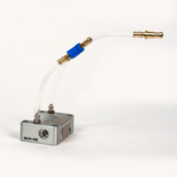 Holld posted an update in the group Corrosion Mapping (CM)4 years ago
 👍1
👍1 -
 ari posted an update in the group Corrosion Mapping4 years ago
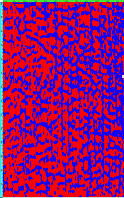
Blue is a back wall 😂
 👍3
👍3 -
Holld started the discussion High temperature corrosion mapping utilizing PAUT method in the forum Corrosion Mapping4 years ago
Have obtained high temperature corrosion mapping sets from Eclipse Scientific and they seem to be working great but we have only flat and not curved wedges for piping therefore cannot inspect anything below 20 inch. Does anybody know a company or supplier that produces high temperature wedges (custom type) that are capable of scanning up to 250 degree Celsius? And any SEMI automated scanners for PAUT. I have seen automated but this option will not work for us.
Your help is appreciated
👍1 -
Holld posted an update in the group Corrosion Mapping (CM)4 years ago
PAUT corrosion mapping with Hydrofom

-
 mohamed-ali-bagath joined the group Corrosion Mapping (CM)4 years ago
 -
 4 years ago
Hi! I am in need of some expert advice.
I have a section of piping that has been inadvertently submerged in water for several years. The pipe was discovered recently with lots of general corrosion on its surface in the form of loose scale and rust.
The remaining pipe thickness must be found. The fear is that if we try to clean a section of the pipe to perform a UT Thickness reading may puncture the pipe. We have some knowledge of others in our industry who have had this happen.
The question I have is what other inspection methods can I use to determine the remaining wall thickness without doing any surface cleaning of the loose scale or rust. Any help would be appreciated.
👍3 -
ANDTS posted an update in the group Corrosion Mapping (CM)4 years ago
The art of PAUT Corrosion Mapping 😀
 👍3
👍3 -
 5 years ago
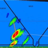
Olympus FlexoForm scanner probe (part number 7.5L64-64X7-FA1) stopped working after a year of use for corrosion mapping and I noticed that plastic protecting the probe has separated from probe itself as per images attached. Now, any recommendations on how to fix this issue?
Would you agree that using heat gun could help or any other way? We did order another probe but would like to fix this one and have it as spare. Also, each cost 17K+ USD.
Your help is much appreciated.
👍2 -
kevlin posted an update in the group Corrosion Mapping (CM)5 years ago

-
kevlin posted an update in the group Corrosion Mapping (CM)5 years ago

Discussions