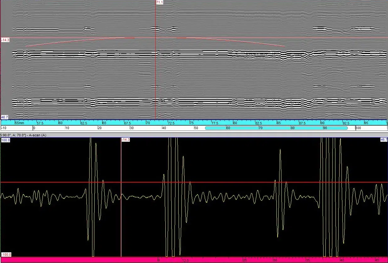
TOFD signals between L-L Backwall and L-Shear Backwall echo.

  • TOFD signals between L-L Backwall and L-Shear Backwall echo.

    Posted by george on 28/11/2021 at 6:03 pm

    In a TOFD image it is recommended (ASME for example) a complete TOFD image including also the shear diffracted signals.
    Where can I find clear and practical guidelines to make decissions and to understand the signals which appears between the Long- Long backwall echo and the Long-Shear backwall echo?
    Thanks in advance.

    arsal replied 3 years, 1 month ago 2 Members · 1 Reply
  • 1 Reply
  • Time of Flight Diffraction (ToFD)

    arsal

    Member
    28/11/2021 at 6:29 pm

    I do not know if there is an absolute method for this. In the book by Charlesworth and Temple there is an image (Figure 5-8) that shows all the arcs for the Compression, Shear and Rayleigh modes and indicates the top and bottom signals for a single planar flaw. This image is a VERY confusing “mess” to look at.
    The authors state that “…it may be necessary to make a judgement as to which are the unconverted compression wave signals from the top and bottom of the defect and then calculate the positions and curve-shapes of all possible mode converted signals.”

Log in to reply.