Successful Ultrasonic Inspection of Austenitic Welds
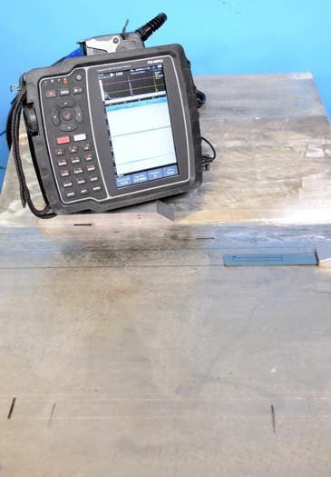
Inspection of Austenitic Welds
Inspection of austenitic steel welds has been performed for many years with varying success. With refinement to our knowledge of the effects of the weld process, and greater awareness of the effects of the material grain structure on our sound fields, we can now more confidently approach these often-challenging inspections.
With a potentially wide range of materials being joined it is critical to approach each inspection with a level of caution. Inspectors are now equipped with many new tools, improved instrumentation, a wide range of transducers, and software which includes predictive modelling.
This paper will convey several logical steps to be performed in order to ensure the success of the inspection. Founded on initial findings, the technician will be able to assemble a virtual check list of steps that will ensure they can convey validation and demonstration of the developed technique.
Keywords: Phased Array, Anisotropic, Heterogeneous
Background
Many factors influence the characteristics of coarse grain welds and several questions need to be answered prior to actually inspecting the weld, along with the adjacent parent material(s). First on the list of questions will be “Is this new construction or an in-service inspection?”
Once we establish the governing codes and specifications that apply, the next series of questions will complete the initial check list providing foundation knowledge. All inspections require foundation knowledge; the more information you have about the material, geometry factors and unique characteristics, the easier and of course, the better the inspection outcome.
As the procedure and techniques are formalized for the application, the first set of known items will be the completion of the technique content; essential variables, detailing the instrument, location and the numerous other key facts pertaining to the weld.
Recording all the required documentation that captures all the known items extending to probes, arrays, wedges, and including coupling, must be part of any inspection process. Coarse grain weld inspection, for our example in this document, will be founded on some standard probes and will include the Dual Matrix Array technology (DMA) [1]. Reporting, and the ability to accurately repeat the inspection, can proceed once all these details are assembled.
Most of the standard content should be founded on an established and effective template format to ensure comprehensive recording is in place. The extra detail is where we want to focus in this paper.
Obtaining the as-built drawings, weld procedure specification (WPS) and any prior ultrasonic inspection or alternative applied NDT method of inspection reports, will all contribute to awareness. For the special considerations when approaching the unique weld conditions that apply to coarse grain weld, additional information can extend to state-of-the-art welding charts and visual records (video) of the actual weld material deposit.
Knowing the height of each weld pass will help determine indication detail; potential defect height will be defined by bead size, founded on the sequence of weld passes and the evaluation of the weld procedure. With this additional detail the inspector can be in a better position to understand what is being seen on the instrument display.
Specialized welding now offers more information and more control of the conditions applied to maintain grain size control (cooler welding process, better control) [2]. Depending on the application and demands of the weld, and the clients’ requirements, the ultrasonic inspection can be relatively easy.
Modifications may involve slight velocity shifts and attenuation might be minimal. However, in other cases the impact of grain size can be significant, resulting in ultrasonic inspection not an option. It is critical that accommodation of the specific conditions for the inspection are resolved early in the process.
As noted, in some scenarios the material being tested can be very problematic with acoustic impedance of the various layers representing significant to almost total reflection at the interface of the layers. For clad and some welds founded on butting layers of austenitic the proposed shear wave inspection for fusion zone boundary is potentially not possible, as the boundary region represents a wall, i.e. no meaningful amount of sound enters.
Once the plan of inspection is in place, the selection of the array and wedge will drive the next steps. Recognize that shear wave pulse echo techniques and the opportunity to reflect or bounce into the weld are simply not viable when working on most coarse grain applications.
Several instruments and several standard probes and arrays have been applied to achieve the inspection outcome. The process of selection is founded on experience but is finalized through experimentation and validation that the proposed inspection approach is in fact viable.
Field validation was performed and will be reported in a separate paper. The goal in this paper is to arrive at an understanding of how to quickly evaluate the weld to enable detection, accurate interpretation and reporting.
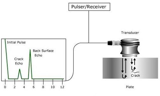
For the discussion application, we will scan weld and adjacent material with a standard zero-degree contact probe. This affords the technician with validation of thickness and will account for weld volume indications along with any attachment or other internals. This scan is valuable and should always be performed early in the process to help confirm assumed detail.
The use of a standard shear wave inspection of the parent material is next and this is targeted at the interrogation of the weld fusion face and provides another level of awareness. The next array is the dual matrix array with a sectorial sweep covering the far side (ID) and near surface (OD) by virtue of offset positions for heavy wall applications and is aided by a wide longitudinal sweep angle set.
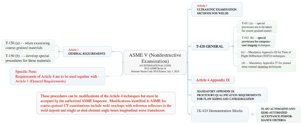
Two groups and two gating positions are applied to help enable interpretation. The unique characteristics of the DMA probe will require some specific steps and although presented briefly here, these arrays demand some special consideration when planning the inspection. ASME 5, Article 1 & Article 4 – provide process and demonstration block criteria, See Figure 1 for logic applied [3].
Figure 1: ASME Approach overview for coarse grain weld inspection
The ASME approach has been applied to address the problematic nature of the weld and parent material. Although other options could apply, the selection of ASME accommodates the demonstration approach and provides precautions that should be taken when performing this form of inspection [4].
The DMA probe will require a specific focal law that will need to be generated and loaded. Focal law files are generated by various third party software. Calibration is achieved using two or more points and is applied to all angles. Founded on the unique wide range of angles utilized for scanning, the more traditional calibration, or wizard options, are not used.
Effects of Geometry
Weld cap, weld root and any geometry factors must be accounted for to enable accurate weld overlay and final optimization of the technique. Producing a weld and component profile will provide the operator with the ability to further record the detail that will help with final plotting and reporting. If the cap has been removed from the weld the option to add additional scans using zero or angle scans directly over the weld and extending into the adjacent parent material, will be beneficial.
This removal of weld cap is ideal and can help with the correlation of angled scans from parent material adjacent to weld. Recognize that with coarse grain materials and clad lined pipe or vessels the option to bounce into the weld is in most cases simply not a viable option. The demonstration block target layout is presented in Figure 2 & 3: dimensions 750mm (29.5 inches) x 500mm (19.6 inches) x 52mm (2”) – tapered to 117mm (4.6”)
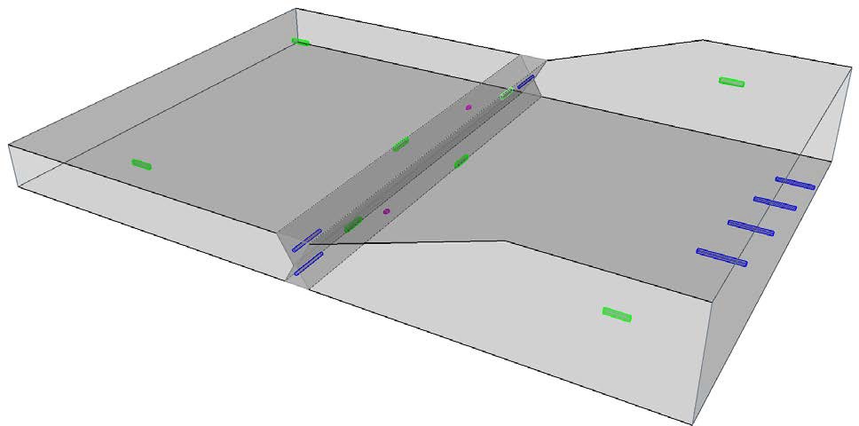
Figure 2: Demonstration block showing targets and weld
Special Consideration for Coarse Grain Weld Inspection
With many questions answered and the technique in place, the next set of questions will enable the inspection to be carried out with confidence. Key will be an understanding of the velocity, velocity changes and attenuation.
Recognize that the proposed approach requires that the demonstration block must have relevant and similar characteristics. The introduction of the targets and a weld will be our means of presenting the client with confidence in the effectiveness of our proposed technique and of course will also provide the technician with the confidence and signal awareness to ensure the successful inspection. Detection and repeatable reporting will result if the checklist has been followed.

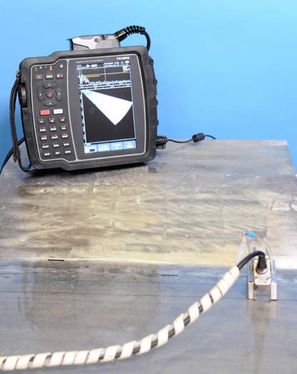
(a) (b)
Figure 3: (a) zero degree contact array inspection (b) shear wave inspection of parent and fusion boundary
The DMA probe is set up and calibrated to achieve several potential modes of detection. The upper angles provide the near surface coverage (so called creeping wave, lateral wave, head wave etc.) and the secondary far surface secondary creep generation is also useful.
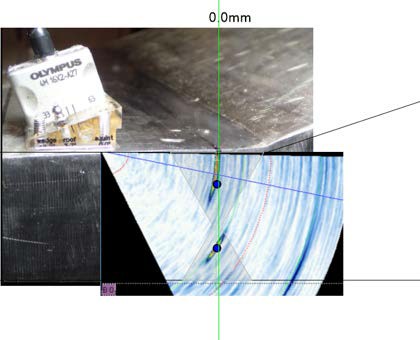
The DMA also enables the direct and some indirect longitudinal wave detection and because of the angles used is prone to generating mode converted shear signals from geometry, targets/indications. Awareness of these signals is a benefit, but can also cause some confusion. Shown in Figure 4 is the ray-trace and calibration founded on the side drilled holes (SDH’s) located within the weld.
Two thickness examples are shown to help understand principles, up to 30mm thick material and over 30mm. Multimode array technology results in target/indication responses potentially arriving at two time intervals, the fast longitudinal or direct longitudinal arrives first with mode converted or secondary shear responses later in time. Thin wall, up to 30mm has clear mode converted signals shown while welds over 30mm have a reduced multiple presence.
It is not practical to acquire very long time intervals to attempt to include the various shear and mode converted signals as thickness increases beyond the noted 30mm. Tip signals and corner trap signals from direct longitudinal and mid- wall discrete responses, those from weld fusion or volume indications, are easy to detect and size with some cautions.
The upper angle responses, those from creep signals, are more challenging, impacted by distance from array and limitations to effectively size for vertical extent. The creep signal weakens with distance and indications at or near the surface will not be discriminated, so alternative NDT disciplines will be beneficial to establish if response is surface breaking.
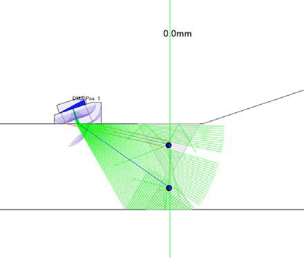
(a) (b)
Figure 4: (a) Ray-trace showing block model (b) Overlay showing S-scan data and alignment of SDH’s
Detection at Upper Angles
Several special requirements have been recognized for the DMA probe use. Listed below are the first step items and these will be further supported with the addition of subsequent steps. A simplified if-then flow has been presented to convey the concepts and as with all check-list approaches, refinement dictated by the specific mandates of the inspection will mature the process. Consider your procedure and process. Adding several more steps in the sizing process can help refine how operators achieve highly repeatable results.

Figure 5: Upper angle surface breaking and sub-surface sizing logic
With the two key conditions noted, near surface and volume/far wall conditions, the sizing logic that is applied needs to accommodate the unique conditions that apply. Upper angles have limitations, in that the response from sub- surface indications can appear to be connected to the surface.
Founded on the established primary reference level (PRL) the scanning gain level can be +6dB or more. It is critical to ensure review for data quality, and the practice of return to PRL as part of the review process will enable the observation of the upper angle responses.
Saturating signals from the lateral wave will appear as surface connected. Return to PRL gain levels in some cases will show clear sub-surface isolation rather than the appearance of surface breaking. The goal is to enable the operators to move quickly through logical steps to enable making the correct calls.
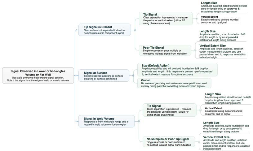
Figure 6: Volume and far wall indications, detection and sizing logic
Conclusion and Recommendation
Although a brief summary for the concept of developing an “if – then” logic has been presented, the individual performing the coarse grain material inspection should enhance this approach with experience gained from each unique inspection. There is no one perfect approach.
- Weld preparation such as flat top or removal of cap and root are beneficial to our inspection
- Shear wave inspection for fusion, along with normal beam inspection of the weld volume and adjacent plate/pipe is required
- DMA probes have shown good performance and excellent SNR for sample welds (cautions still apply – inspection of some welds will not be possible)
- Working with ray-trace or predictive modeling can help the operator account for various signal times
REFERENCES
- Olympus Webinar: Setup and Use of Olympus Dual Matrix Array Probes with OmniScan MX2 Flaw Detector – Getting Started: http://www.olympus-ims.com/en/resources/webinars/setup-and-use-of-olympus-dual-matrix- array-probes-with-omniscan-mx2-flaw-detector-getting-started/
- Technical Evaluation of Ultrasound Phased Array Inspection in Welded Joints of AISI 304L Austenitic Stainless Steel, Ramon Ferreira Ferreira1, Maurício Saldanha Motta2, Lincoln Silva Gomes3, Maurício Ogawa4, André,
Rocha Pimenta5
- Section V ASME Boiler and Pressure Vessel Code
- ISO 22825 Non-destructive testing of welds — Ultrasonic testing — Testing of welds in austenitic steels and nickel-based alloys

Responses