662 members · Public group

Visitor
Started 4 years ago
Hi,
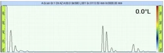
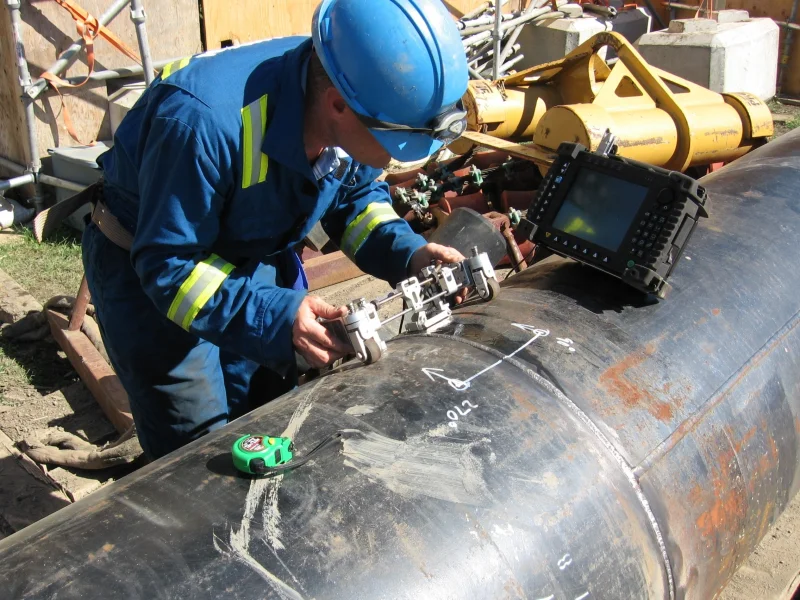
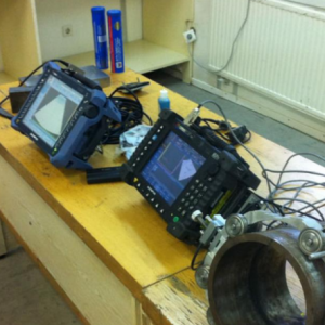
The manufacturer of the Phased Array equipment that I use indicates to calibrate the Sensitivity through the 1.5mm diameter side hole of the V1 block, but for acquisitions in large thicknesses (Example: butt joint 46 mm) the Sensitivity calibration in the 1.5mm diameter side hole of the V1 does not prove to be effective.
We are using a block of the same P-number family of the base metal with an approximate thickness of 46mm, a side hole with a diameter of 3.2mm and a depth of 38mm and the acquisitions have been very satisfactory, finding all the defects of the mockup.
Is this procedure correct, or is there something better I can do?
Regards.
1 reply

35 minutes ago
Your approach is sound practice. What you are doing — calibrating sensitivity using a test block that mimics the actual inspection geometry — is in line with the principle that sensitivity calibration should be representative of the component being inspected.
The 1.5 mm side hole in the V1 block gives you a baseline and is useful for equipment checks, but it does not account for the acoustic behaviour of the 46 mm thickness you are working with. Sound attenuation, near-field effects, and beam spread all change with thickness, so a calibration block that matches your actual test piece thickness and material is more relevant. This is why your 3.2 mm hole in a 46 mm block is giving you better defect detection on the mockup — it reflects the real inspection conditions.
To formalize this:
- Check your inspection procedure or Written Practice to see what it specifies for sensitivity calibration. Some procedures allow or require thickness-matched blocks; others may specify a standard reference.
- If your Written Practice does not address this, work with your Level III or procedure author to document your calibration method.
- Keep records of both calibrations — the V1 baseline and your thickness-matched block — so you can demonstrate consistency and traceability.
- Make sure your 46 mm block is from the same material family and condition as the actual welds you are inspecting, and that the side hole is at a representative depth.
This is good troubleshooting. The fact that your mockup results are satisfactory with the thickness-matched block is strong evidence that your method is working. Document it and keep it repeatable.
Sign in to reply to this discussion.


 Join free
 Register your company
 Sign in